
Conveying device for decorative plates

A technology of conveying device and decorative plate, applied in the direction of conveyor, conveyor objects, transportation and packaging, etc., can solve the problems of low work efficiency, inconvenience, manual handling, etc.

Active Publication Date: 2021-02-09
SHANDONG VOCATIONAL COLLEGE OF SCI & TECH
View PDF5 Cites 2 Cited by
  • Summary
  • Abstract
  • Description
  • Claims
  • Application Information

AI Technical Summary

Problems solved by technology

Since the conveyor belt is usually conveyed in a horizontal line, and the fixing of the board is generally carried out by installing symmetrical fixing blocks on the conveyor belt, this method can only convey the board in the horizontal direction. For the board that needs to be placed on the top, it needs to Manual handling, low work efficiency
[0003] In summary, there are obviously inconveniences and defects in the actual use of the existing technology, so it is necessary to improve

Method used


Image

  • Conveying device for decorative plates
  • Conveying device for decorative plates
  • Conveying device for decorative plates

Examples


Embodiment Construction

[0025] In order to make the objectives, technical solutions and advantages of the present invention clearer, the present invention will be described in further detail below in conjunction with the accompanying drawings and embodiments. It should be understood that the specific embodiments described here are only used to explain the present invention and are not intended to limit the invention.

[0026] It should be noted that, in the description of the present invention, terms such as "upper", "lower", "left", "right", "inner", "outer" and other indicated directions or positional relationships are based on the terms shown in the accompanying drawings. The direction or positional relationship shown is only for convenience of description, and does not indicate or imply that the device or element must have a specific orientation, be constructed and operated in a specific orientation, and thus should not be construed as limiting the present invention.

[0027] In addition, it shou...


PUM


Abstract

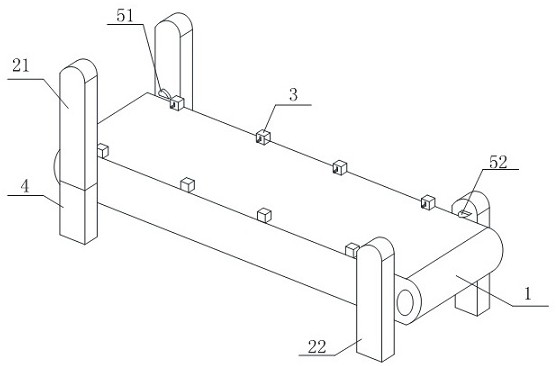
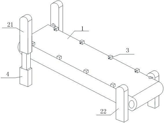
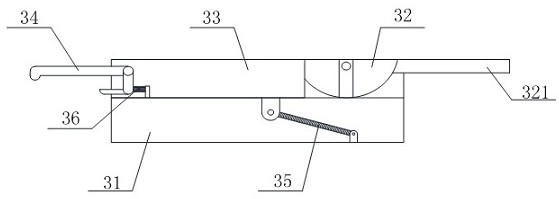
The invention belongs to the technical field of conveying, and provides a conveying device for decorative plates. The conveying device comprises a conveying belt, a supporting device and a clamping device. The supporting device comprises an upper supporting device body and a lower supporting device body, and the lower supporting device body comprises a lower supporting plate and a compaction blocklocated on the lower supporting plate. The conveying belt sleeves a driving wheel and a driven wheel, and the driving wheel is connected with a driving part. The clamping device comprises a base, aneccentric part, a sliding block, an extrusion part and a reset part, the two ends of the reset part are correspondingly connected with the sliding block and the base, the eccentric part is connected with the base through a vertical plate, the eccentric part comprises an arc-shaped section and a right-angle section, and an accommodating space is formed in the sliding block. The extrusion part comprises an upper extrusion rod, a vertical rod and a lower extrusion rod, the upper extrusion rod is connected with the lower extrusion rod through the vertical rod, and an elastic piece is installed between the lower end of the vertical rod and the sliding block. According to the conveying device for the decorative plates, rectangular decorative plates can be effectively conveyed, potential safety hazards are reduced while the conveying efficiency is improved, and meanwhile, inclined conveying can be achieved at different angles.

Description

technical field [0001] The invention relates to the technical field of material conveying, in particular to a conveying device for decorative boards. Background technique [0002] In the process of building decoration, for large-scale interior decoration, it is necessary to use decorative boards, that is, rectangular wooden boards to build sides or cover the top. When conveying decorative boards, manual handling or conveyor belt transportation is generally used, and manual handling is mostly used. For the decoration of smaller houses, the conveyor belt is used for transportation, and it is mostly used in large workshops, etc., and the conveyor belt is used to transport the decorative panels located on the edge of the factory building to the interior for installation and fixing. Since the conveyor belt is usually conveyed in a horizontal line, and the fixing of the board is generally carried out by installing symmetrical fixing blocks on the conveyor belt, this method can onl...

Claims


Application Information

Patent Timeline
Patent Type & Authority Applications(China)
IPC IPC(8): B65G15/58B65G41/00B65G15/30B65G23/04
CPCB65G15/30B65G15/58B65G23/04B65G41/002B65G2201/022
Inventor 翟志杰
Owner SHANDONG VOCATIONAL COLLEGE OF SCI & TECH
Learn More