Mechanical walking stick for helping aged
A mechanical and crutch technology, applied in the direction of walking sticks, travel goods, applications, etc., can solve the problems of difficult operation, unfavorable users, single stick structure, etc., and achieve convenient adjustment operation, convenient and practical carrying, and fast storage and carrying Effect
- Summary
- Abstract
- Description
- Claims
- Application Information
AI Technical Summary
Problems solved by technology
Method used
Image
Examples
Embodiment 1
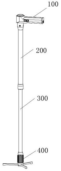
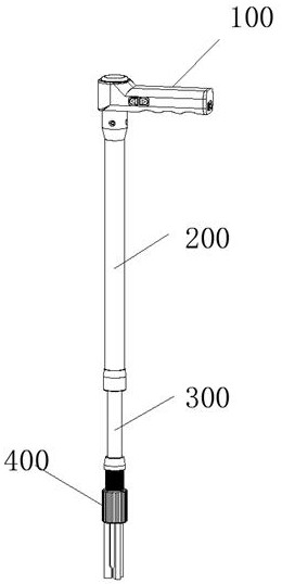
[0044] Please see Figure 4-5 , the grip handle 100 is a hollow structure, the inner cavity of the grip handle 100 is provided with a battery 110 and a motor drive board 120, the battery 110 is a rechargeable lithium battery, and is equipped with a corresponding charging circuit board, not shown in the figure, the battery 110 and the motor drive board 120 The motor drive board 120 is electrically connected to provide electric energy, and the side wall of the handle 100 is embedded with an adjustment button 130, and the adjustment button 130 is electrically connected to the motor drive board 120 for controlling the forward and reverse rotation of the motor;
[0045] The end of the grip handle 100 is provided with a handle end cover 140, and a charging connection seat 150 is embedded on the handle end cover 140, and the charging connection seat 150 is electrically connected with the charging circuit board for charging with an external transformer charger. , in order to confirm t...
Embodiment 2
[0048] Please see Figure 5-6 , the upper end of the fixed rod 200 is socketed and fixed with the grip handle 100, the inner cavity of the fixed rod 200 is provided with a drive motor 210 and a reducer 220, and the bottom output end of the reducer 220 is connected with a transmission screw 240 through a coupling 230, The outer wall of the transmission screw 240 is screwed with a lifting nut 250; the top of the fixed rod 200 is provided with a fixed rod end cover 260, the driving motor 210 is coaxially connected with the reducer 220, and a motor is arranged between the reducer 220 and the inner wall of the fixed rod 200. Install the sleeve 270, the end surface of the motor installation sleeve 270 is fixedly installed with the reducer 220 by screws, the side wall is fixedly installed with the outer wall of the fixed rod 200 by screws, and the outer wall of the fixed rod 200 is connected with the handle 100. There is a wire hole 280; the driving motor 210 and the reducer 220 are ...
Embodiment 3
[0051] Please see Figure 7-8 , the supporting claw frame 400 is fixed on the bottom end of the telescopic rod 300, three groups of supporting claws 410 that can be unfolded or closed at the same time are hinged below the supporting claw frame 400, the supporting claw frame 400 includes a columnar main body 420, and the top of the columnar main body 420 is provided with a The connecting hole 430 at the bottom end of the rod 300 is sleeved, and the middle part of the outer wall of the columnar body 420 is provided with a section of external thread section 440 along the axial direction. The threaded section 440 is screwed and can be adjusted up and down. The bottom of the columnar body 420 is provided with three groups of hinged grooves 460 in a circumferential array. There is a torsion spring slot 480 on the inner side of the upper end of the torsion spring slot 480, and a spring pressure torsion spring 490 is arranged in the torsion spring slot 480. The spring pressure torsion...
PUM
 Abstract
Description
Claims
Application Information
 - R&D
- Intellectual Property
- Life Sciences
- Materials
- Tech Scout
- Unparalleled Data Quality
- Higher Quality Content
- 60% Fewer Hallucinations
Browse by: Latest US Patents, China's latest patents, Technical Efficacy Thesaurus, Application Domain, Technology Topic, Popular Technical Reports.
© 2025 PatSnap. All rights reserved.Legal|Privacy policy|Modern Slavery Act Transparency Statement|Sitemap|About US| Contact US: help@patsnap.com


