Insulation type power equipment detection terminal equipment
What is Al technical title?
Al technical title is built by PatSnap Al team. It summarizes the technical point description of the patent document.
A technology for electrical equipment and detection terminals, which is applied to the parts of electrical measuring instruments, measuring electricity, measuring devices, etc., can solve the problems of messy data lines, opening up space, winding, etc., so as to avoid data line winding and facilitate installation and disassembly. , the effect of convenient use
Active Publication Date: 2021-02-12
RED PHASE INC
View PDF11 Cites 2 Cited by
Summary
Abstract
Description
Claims
Application Information
AI Technical Summary
This helps you quickly interpret patents by identifying the three key elements:
Problems solved by technology
Method used
Benefits of technology
Problems solved by technology
[0002] Power equipment detection terminal equipment is a terminal used to detect power equipment, but the existing terminals lack the necessary wire harness devices, resulting in messy entanglement of data lines, which is inconvenient to use, and the existing terminals lack the necessary probes Accessories. When testing different types of electrical equipment, a single type of probe cannot meet the demand. The existing terminal box cover is flip-type, which takes up more space when opened.
Method used
Image
Click on the blue label to locate the original text in one second.
Reading with bidirectional positioning of images and text.
Examples
Embodiment Construction
[0027] The following will clearly and completely describe the technical solutions in the embodiments of the present invention with reference to the accompanying drawings in the embodiments of the present invention. Obviously, the described embodiments are only some, not all, embodiments of the present invention. Based on the embodiments of the present invention, all other embodiments obtained by persons of ordinary skill in the art without making creative efforts belong to the protection scope of the present invention.
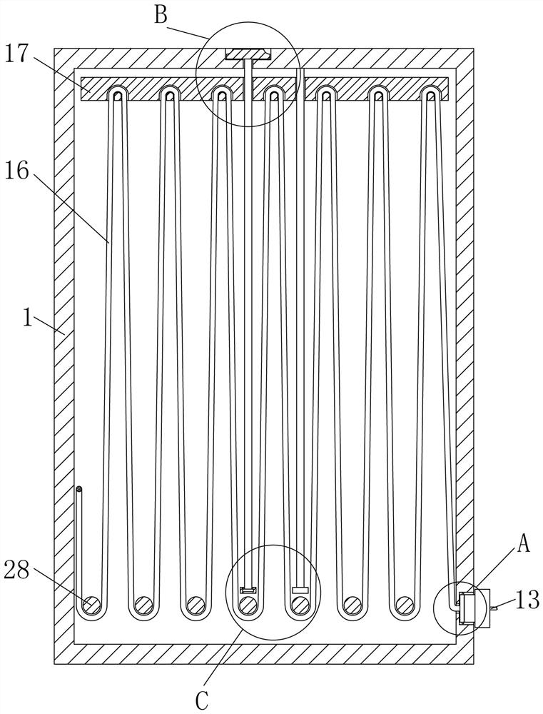
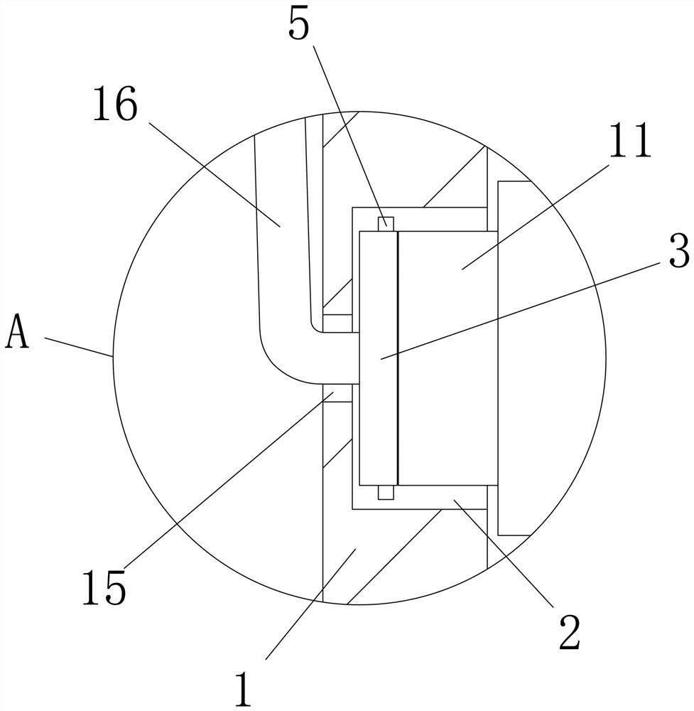
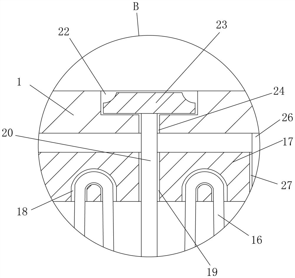
[0028] see Figure 1-12, the present invention provides a technical solution: an insulated power equipment detection terminal equipment, including a casing 1, a first receiving groove 2, a connecting plate 3, a first limiting groove 4, a first button 5, and a first spring 6 , the first chute 7, the connecting rod 8, the first block 9, the socket 10, the sleeve 11, the first card slot 12, the probe 13, the socket 14, the first through hole 15, the data line 16,...
PUM
Abstract
The invention discloses an insulation type power equipment detection terminal equipment. The equipment comprises a casing, a first accommodating groove, a connecting plate, a first limiting groove, asocket, a sleeve, a first clamping groove, a probe, a jack, a screw rod, a first fixing block, a second accommodating groove, a knob, a second through hole, a second fixing block, a guide rod, a guidehole, a wrapping post, a partition plate, a wire outlet hole, a terminal body, an accessory chamber, a placement groove, a sliding cover, a second sliding block, a second button, an elastic piece, asecond clamping block, a third accommodating groove, a limiting box, a top block, a limiting ring and a second spring. Compared with an existing detection terminal equipment, the detection terminal equipment is provided with a wire bunching mechanism, data lines can be automatically stored in order, the data lines are prevented from being wound, use is convenient, the replaceable probe is designed, the mounting base of the probe is a clamping structure, mounting and dismounting are convenient, the sliding cover is designed, opening is convenient, an extra space is not occupied, and the equipment can be conveniently used in a narrow position.
Description
technical field [0001] The invention relates to the technical field of power equipment detection, in particular to an insulated power equipment detection terminal device. Background technique [0002] Power equipment detection terminal equipment is a terminal used to detect power equipment, but the existing terminals lack the necessary wire harness devices, resulting in messy entanglement of data lines, which is inconvenient to use, and the existing terminals lack the necessary probes For accessories, when testing different types of electrical equipment, a single type of probe cannot meet the demand. The existing terminal box cover is flip-type, which takes up more space when opened. Contents of the invention [0003] The purpose of the present invention is to provide an isolated electric device detection terminal device to solve the problems raised in the above-mentioned background technology. [0004] In order to solve the above technical problems, the present invention...
Claims
Application Information
Patent Timeline
Application Date:The date an application was filed.
Publication Date:The date a patent or application was officially published.
First Publication Date:The earliest publication date of a patent with the same application number.
Issue Date:Publication date of the patent grant document.
PCT Entry Date:The Entry date of PCT National Phase.
Estimated Expiry Date:The statutory expiry date of a patent right according to the Patent Law, and it is the longest term of protection that the patent right can achieve without the termination of the patent right due to other reasons(Term extension factor has been taken into account ).
Invalid Date:Actual expiry date is based on effective date or publication date of legal transaction data of invalid patent.