A linear rod wire binding device
A linear rod and wire technology, applied in the field of linear rod wire binding devices, can solve the problems that construction personnel are not easy to get started, the binding time is long, and the binding is not firm, and the effect of reducing the difficulty of binding, shortening the construction time, and reducing the power outage time is achieved.
- Summary
- Abstract
- Description
- Claims
- Application Information
AI Technical Summary
Problems solved by technology
Method used
Image
Examples
Embodiment 1
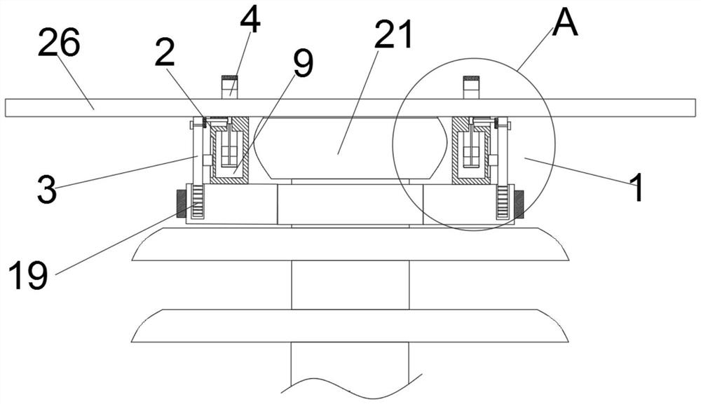
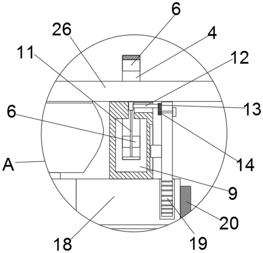
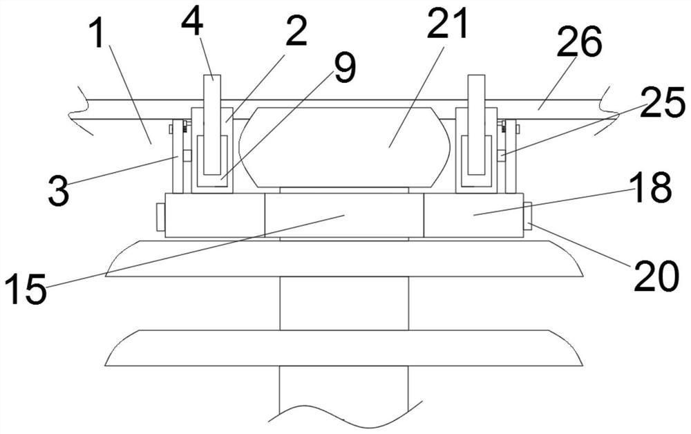
[0024] see Figure 1 to Figure 6 , a linear rod wire binding device provided by the present invention includes a wire clamping assembly 1 and a fixing assembly 15, the fixing assembly 15 is used to be fixed at the neck of the porcelain bottle 21, and the present invention can be fixed at the neck of the porcelain bottle 21 , wherein the wire clamping assembly 1 is a pair, respectively located on both sides of the porcelain bottle 21, the wire clamping assembly 1 includes a support seat 2, a fixed plate 3 and a clamping ring 4, and the support seat 2 is provided with a The support groove 5 of the wire 26, the support groove 5 of the support seat 2 cooperates with the top groove of the porcelain bottle 21 to play the role of placing the support wire 26, the support seat 2 is fixedly connected with the fixed assembly 15, and the fixed plate 3 It can be adjusted up and down and connected to the fixed assembly 15, and the clamping ring 4 can be adjusted up and down, so that the cla...
Embodiment 2
[0029] see Figure 1 to Figure 6 The difference between this embodiment and Embodiment 1 is that the fixing assembly 15 includes a first fixing ring 16 and a second fixing ring 17, one end of the first fixing ring 16 is hinged to one end of the second fixing ring 17, The free end of the fixing ring is detachably connected with the free end of the second fixing ring 17 . It is convenient to fix the present invention on the bottle neck of the porcelain bottle 21, wherein the detachable connection can be through bolt connection.
[0030] Specifically, the first fixing ring 16 and the second fixing ring 17 are connected with a fixing base 18, the support base 2 is fixed on the fixing base 18, and the fixing plate 3 can be adjusted up and down and connected to the fixing base 18. on the fixed seat 18. It plays the role of supporting and fixing the support seat 2, and is convenient for adjusting the up and down movement of the fixing plate 3, so that the clamping groove 6 cooperat...
Embodiment 3
[0032] see Figure 1 to Figure 6 , the difference between this embodiment and Embodiment 1 is that the lower end of the fixed plate 3 is provided with tooth lines 19, and the fixed seat 18 is rotatably connected with an adjustment gear (not marked), and the adjustment gear (not marked) Mesh with the teeth 19 , the adjustment gear (not shown) is connected with an adjustment disc 20 . When adjusting the fixed plate 3 to move up and down, turn the adjusting disc 20, so that the adjusting disc 20 drives the adjusting gear (not marked) to rotate, and the adjusting gear (not marked) drives the fixed plate 3 to move down, so that the clamping groove 6 is stable The lead wire 26 is clamped.
[0033] Specifically, clamping plates 22 are provided on both sides of the notches of the plurality of clamping slots 6 , and slots 23 corresponding to the clamping plates 22 are provided on both sides of the support slot 5 . The clamping plates 22 arranged on both sides of the clamping groove 6...
PUM
 Abstract
Description
Claims
Application Information
 - R&D
- Intellectual Property
- Life Sciences
- Materials
- Tech Scout
- Unparalleled Data Quality
- Higher Quality Content
- 60% Fewer Hallucinations
Browse by: Latest US Patents, China's latest patents, Technical Efficacy Thesaurus, Application Domain, Technology Topic, Popular Technical Reports.
© 2025 PatSnap. All rights reserved.Legal|Privacy policy|Modern Slavery Act Transparency Statement|Sitemap|About US| Contact US: help@patsnap.com


