Static switch parallel connection method

A technology of static switching and parallel connection, which is applied in the direction of AC network circuits, electrical components, circuit devices, etc., which can solve problems such as power interruption, affecting the normal operation of equipment, and long switching process time, and achieve the effect of improving reliability

Pending Publication Date: 2021-02-12
合肥联信电源有限公司
View PDF0 Cites 0 Cited by
  • Summary
  • Abstract
  • Description
  • Claims
  • Application Information

AI Technical Summary

Problems solved by technology

[0005] In this circuit mode, when the thyristor device fails or the static switch control board fails, the static switch will have no output, only manual switching to bypass maintenance, the entire switching process takes a long time, and the back-end load will be switched during the switching process. There is no power output, resulting in power interruption, which affects the normal operation of important back-end equipment

Method used


Image

  • Static switch parallel connection method
  • Static switch parallel connection method
  • Static switch parallel connection method

Examples


Embodiment 1

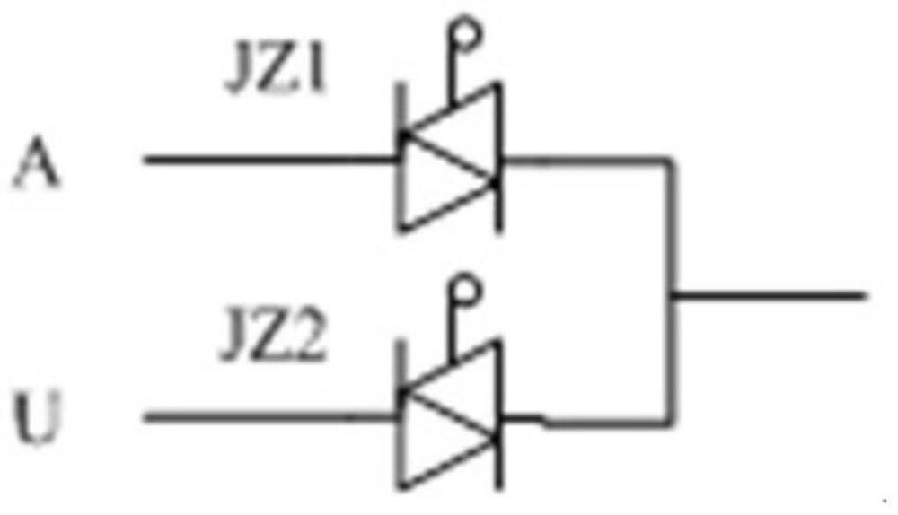
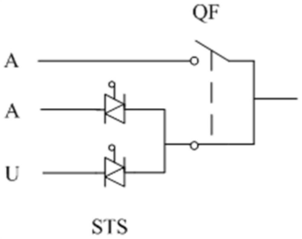
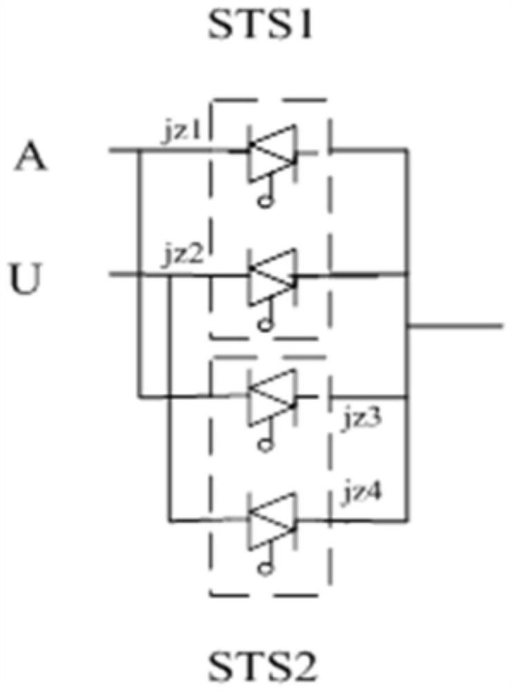
[0020] see Figure 3-4 , a parallel connection method of static switches, including setting two sets of static switches STS1 and STS2 in parallel, each set of static switches is composed of six thyristors, a set of control board PCB and a set of thyristor driver board SQ, the static switch STS1 The six thyristors are divided into three and three components into the main power thyristor group JZ1 and the backup power thyristor group JZ2, and the six thyristors in the static switch STS2 are composed of three and three parts into the main power thyristor group JZ3 and the backup power thyristor group JZ4, in which the static switch STS1 is a common switch, static switch STS2 is a backup switch, the static switch STS1 is connected to the main power supply circuit A, the static switch STS2 is connected to the backup power supply circuit U, and the output end of the static switch STS1 and the output end of the static switch STS2 are connected together in parallel.

[0021] Both the ...

Embodiment 2

[0026] On the basis of Embodiment 1, the control board PCB has an independent power supply GB, and the power supply GB is a storage battery. When adjusting and controlling work through the control board PCB, the power supply GB can be used when the static switch is not connected to the main power supply A or the standby power supply. When the power supply U is connected, it provides initial power supply; meanwhile, the control board PCB also has a three-phase current circuit.


PUM


Abstract

The invention discloses a static switch parallel connection method. According to the method, two sets of static switches STS1 and STS2 which are arranged in parallel are adopted; each set of static switch is composed of six thyristors, a set of control board PCB and a set of thyristor driving board SQ; the six thyristors in the static switch STS1 are divided into a main electric thyristor group JZ1 and a standby electric thyristor group JZ2, wherein each thyristor group comprises three thyristors; the six thyristors in the static switch STS2 are divided into a main electric thyristor group JZ3and a standby electric thyristor group JZ4, wherein each thyristor group comprises three thyristors; the static switch STS1 is a common switch; the static switch STS2 is a standby switch; the staticswitch STS1 is connected with a main power supply circuit A; the static switch STS2 is connected with a standby power supply circuit U; and the output end of the static switch STS1 and the output endof the static switch STS2 are connected in parallel. Compared with a single static switch mode, the double static switch parallel mode adopted by the method can assist in solving the problem that thefault of a single static switch affects the power supply of a rear-end important load, and can improve the reliability of the static switches.

Description

technical field [0001] The invention relates to a static switch, in particular to a method for parallel connection of a static switch. Background technique [0002] The static switch is an automatic switching device that realizes two different AC power sources (frequency, phase, and amplitude may be different). Automatic or manual switching process of main and standby power sources. [0003] The static switch has the following advantages: 1. No contact jumping; 2. Low mechanical noise; 3. Small radio frequency interference; 4. Since there are no movable parts that will be damaged, it is easy to maintain; 6. Not affected by shock and vibration; 7. Can be installed in any direction; 8. High switching speed; 9. Small size in many applications. [0004] The main circuit of the existing static switch such as figure 1 As shown, in the general static switch products, one thyristor is set for the main power and the backup power as the switching device, and the bypass maintenance ...

Claims


Application Information

Patent Timeline
Patent Type & Authority Applications(China)
IPC IPC(8): H02J3/00
CPCH02J3/0073
Inventor 李多山刘晖
Owner 合肥联信电源有限公司
Why Eureka
Try Eureka