Supercharge Your Innovation With Domain-Expert AI Agents!

Rear location detection mechanism for computer numeric control bending robot

A detection mechanism and robot technology, applied in metal processing, metal processing equipment, manufacturing tools, etc., can solve the problem of inability to judge the position and position of the sheet metal

Pending Publication Date: 2021-02-19
黄石华强数控机床有限公司
View PDF0 Cites 1 Cited by
  • Summary
  • Abstract
  • Description
  • Claims
  • Application Information

AI Technical Summary

Problems solved by technology

[0004] The purpose of the present invention is to solve the shortcomings of the inability to judge the position and position of the sheet material in the prior art, and propose a position detection mechanism for the rear positioning of the CNC bending robot

Method used


Image

  • Rear location detection mechanism for computer numeric control bending robot
  • Rear location detection mechanism for computer numeric control bending robot
  • Rear location detection mechanism for computer numeric control bending robot

Examples


Embodiment 1

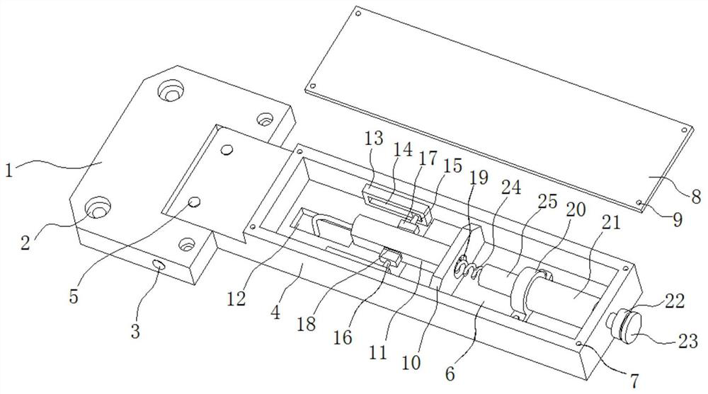
[0021] refer to Figure 1-4 , a rear positioning position detection mechanism of a numerically controlled bending robot, including a fixing part, a mounting support 4 is rotatably connected to the fixing part, and a horizontal adjustment top wire 5 is connected to the side of the mounting support 4 close to the fixing part, and the installation The upper end of the bearing 4 is provided with a groove 6, and a displacement sensor bracket 10 is connected in the groove 6, and a high-precision displacement sensor 11 is connected on the displacement sensor bracket 10, and a strip-shaped hole 12 is provided at the bottom of the groove 6. The hole 12 is convenient for the high-precision displacement sensor 11 to be connected to the robot host computer through a wire, and the inner two sides of the groove 6 are connected with a limit mechanism, and one side of each limit mechanism is in contact with the high-precision displacement sensor 11, and the limit mechanism is The high-precisi...

Embodiment 2

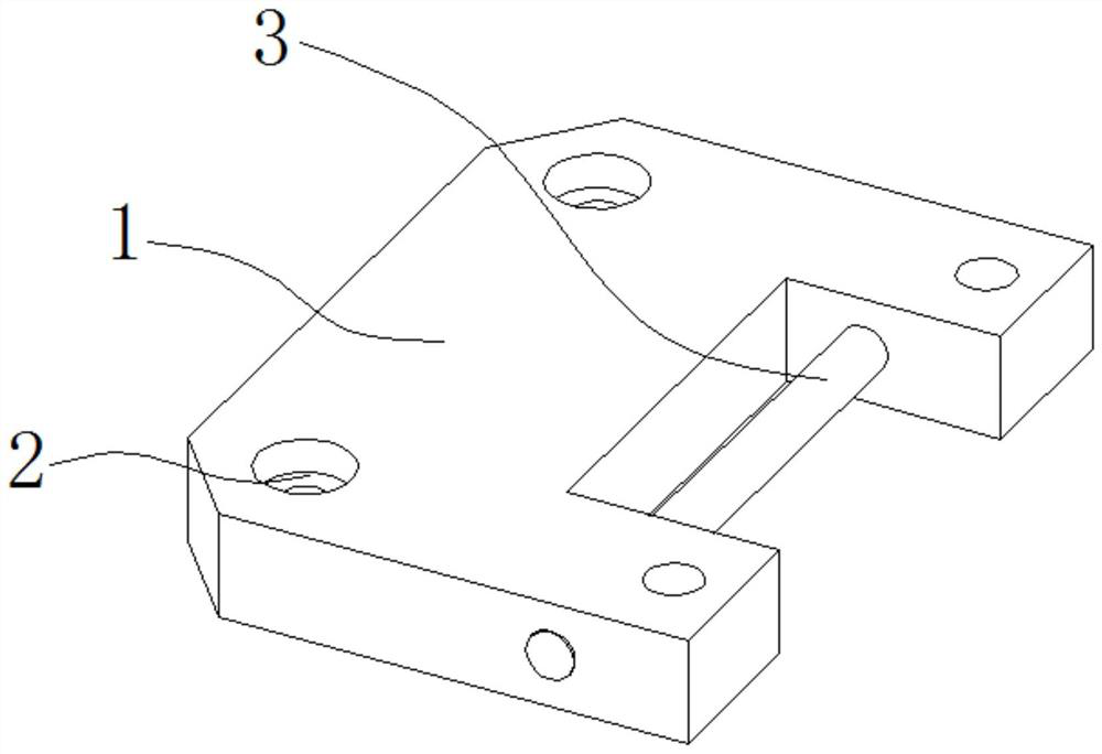
[0024] refer to Figure 1-4 , as another preferred embodiment of the present invention, the difference from Embodiment 1 is that the fixing member includes a fixing seat 1, and both sides of the upper end of the fixing seat 1 are provided with mounting holes 2, and a latch 3 is inserted on the fixing seat 1, and the latch 3 Connect the mounting support 4, and the bolts pass through the mounting hole 2 to fix the fixing seat 1 on the back gauge mechanism of the bending machine.

Embodiment 3

[0026] refer to Figure 1-4 , as another preferred embodiment of the present invention, the difference from Embodiment 1 is that the limit mechanism includes a fixed frame 13, the fixed frame 13 is connected to the mounting support 4, and a chute 14 is provided on the fixed frame 13, and the chute 14 can be The slide block 15 is connected with the slide block 15, and the slide block 15 is connected with a fixed rod 16, and the end of the fixed rod 16 away from the slide block 15 is connected with a limit block 17, and the limit block 17 is connected with an elastic pad 18, and one side of the elastic pad 18 In contact with the high-precision displacement sensor 11, the movement of the high-precision displacement sensor 11 drives the limit block 17 to move, and the limit block 17 drives the slider 15 to slide in the chute 14 through the fixed rod 16, and under the limit of the limit block 17 , the high-precision displacement sensor 11 moves smoothly in the horizontal direction....


PUM


Abstract

The invention relates to the technical field of detection mechanisms, in particular to a rear location detection mechanism for a computer numeric control bending robot. The mechanism comprises a fixing piece; the fixing piece is rotationally connected with an installation support base; a displacement sensor support is connected with a high-precision displacement sensor; and a through hole is formed in the displacement sensor support. A bearing pedestal is connected in a groove; the bearing pedestal is connected with a linear bearing; the end, outside the installation support base, of the linear bearing is connected with a detection head; the end, away from the detection head, of the linear bearing is connected with a spring; and one end of the spring makes contact with the high-precision displacement sensor. The high-precision displacement sensor is pushed by the spring to move towards the fixing piece; the high-precision displacement sensor stably moves under limiting of a limiting mechanism, and therefore, displacement is generated; the high-precision displacement sensor measures the displacement and uploads the displacement to an upper computer of the robot in a form of digitalsignals; the in-place situation and the position situation of a plate material are judged; and the robot and the bending machine are directed to perform next actions.

Description

technical field [0001] The invention relates to the technical field of detection mechanisms, in particular to a rear positioning position detection mechanism of a numerically controlled bending robot. Background technique [0002] The bending robot uses the equipped mold to bend the metal sheet in the cold state into various geometric cross-sectional shapes. Front and rear adjustment, left and right adjustment, pressure tonnage adjustment and slider approaching working speed adjustment, etc. It can make the bending robot conveniently realize the actions of sliding block down, inching, continuous, holding pressure, returning and stopping halfway, and complete the bending of multiple elbows with the same angle or different angles in one feeding. [0003] When the existing bending robot is positioning the bending sheet, it cannot judge the position and position of the sheet, and the command robot and bending machine cannot complete the next step. Contents of the invention ...

Claims


Application Information

Patent Timeline
Patent Type & Authority Applications(China)
IPC IPC(8): B21D11/22B21C51/00
CPCB21D11/22B21C51/00
Inventor 李望安蔡华
Owner 黄石华强数控机床有限公司
Features
  • R&D
  • Intellectual Property
  • Life Sciences
  • Materials
  • Tech Scout
  • Unparalleled Data Quality
  • Higher Quality Content
  • 60% Fewer Hallucinations
Learn More