Vacuum tank cover opening paint dipping device

A technology of a cap opening device and a vacuum tank, which is applied to the opening of vacuum seals, etc., can solve the problems of low efficiency and large space occupation, and achieve the effect of increasing height, saving space, and facilitating opening or closing.

Inactive Publication Date: 2021-02-19
湘潭林海机械制造有限公司
View PDF0 Cites 0 Cited by
  • Summary
  • Abstract
  • Description
  • Claims
  • Application Information

AI Technical Summary

Problems solved by technology

[0002] The rotating shaft of the rotary cap opening device is installed on the tank body. After the ...

Method used


Image

  • Vacuum tank cover opening paint dipping device
  • Vacuum tank cover opening paint dipping device
  • Vacuum tank cover opening paint dipping device

Examples


Embodiment Construction

[0023] Example embodiments will now be described more fully with reference to the accompanying drawings. Example embodiments may, however, be embodied in many forms and should not be construed as limited to the embodiments set forth herein; rather, these embodiments are provided so that this patent will be thorough and complete, and will fully convey the concepts of example embodiments. communicated to those skilled in the art. The same reference numerals in the drawings denote the same or similar structures, and thus their detailed descriptions will be omitted.

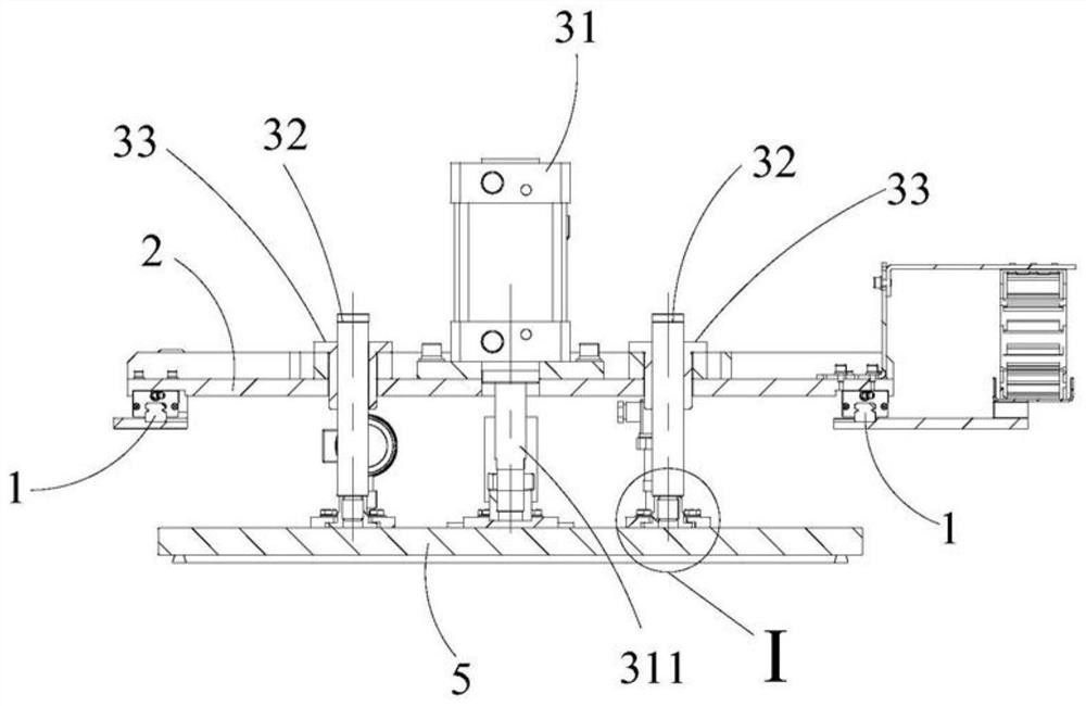
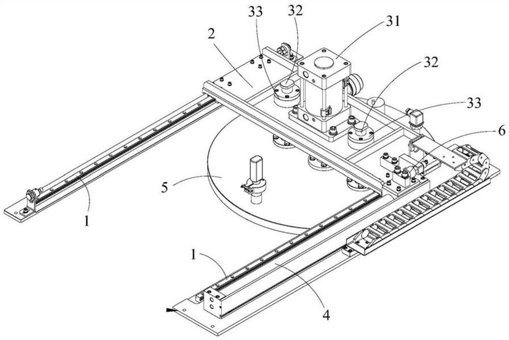
[0024] see figure 1 and figure 2 , figure 1 It is a schematic diagram of a vacuum tank lid opening device according to an embodiment of the patent of the present invention, figure 2 It is a schematic diagram of the vacuum tank opening device patented by the present invention when viewed from another angle. The patent of the present invention discloses a vacuum tank cover opening device, which is used to move t...


PUM


Abstract

The invention provides a vacuum tank cover opening paint dipping device. The vacuum tank cover opening paint dipping device comprises a horizontal guide rail, a moving device, a lifting device and a driver, wherein the horizontal guide rail is horizontally arranged above a vacuum tank; the moving device is arranged on the horizontal guide rail; the lifting device is arranged on the moving device,and is connected with a tank cover; and the driver is connected with the moving device, and drives the moving device to move along the horizontal guide rail.

Description

technical field [0001] The patent of the present invention relates to a vacuum tank cover-opening and dipping device. Background technique [0002] The rotating shaft of the rotary cap opening device is installed on the tank body. Generally, the tank cap can only be removed manually after the cap is uncapped, which is inefficient and takes up a lot of space. The above information disclosed in this Background section is only for enhancement of understanding of the background of the invention and therefore it may contain information that does not form the prior art that is already known in the art to a person of ordinary skill in the art. Contents of the invention [0003] One object of the patent of the present invention is to overcome the shortcomings of the above-mentioned prior art, and provide a vacuum tank lid opening device that saves space and can conveniently open or close the tank lid. [0004] Another object of the patent of the present invention is to provide a ...

Claims


Application Information

Patent Timeline
IPC IPC(8): B67B7/20
CPCB67B7/20
Inventor 明昆
Owner 湘潭林海机械制造有限公司
Why Eureka
Try Eureka