Separation device for waste incineration

A separation device and waste incineration technology, applied in incinerators, combustion methods, combustion types, etc., can solve the problems of inability to separate slag, insufficient separation, etc., and achieve the effect of reducing the filtering effect and improving the separation effect.

Inactive Publication Date: 2021-02-19
西安中威环境技术有限公司
View PDF1 Cites 0 Cited by
  • Summary
  • Abstract
  • Description
  • Claims
  • Application Information

AI Technical Summary

Problems solved by technology

However, in the above-mentioned sewage sludge separation device for garbage incineration, it cannot separate the slag after garbage incineration better, and some small stones or other larger impurities remain in the slag, and the separation is not sufficient.

Method used


Image

  • Separation device for waste incineration
  • Separation device for waste incineration
  • Separation device for waste incineration

Examples


Embodiment 1

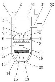
[0025] Example 1 as Figure 1-4 As shown, the waste incineration separation device according to the embodiment of the present invention includes an incinerator body 1, the top of the incinerator body 1 is provided with a feed pipe 2, and the top in the incinerator body 1 is provided with an incineration chamber 3, and the incineration chamber The bottom end of 3 is provided with revolving door 4, and the bottom end of incineration chamber 3 is provided with the refrigeration block 5 that is arranged symmetrically, and one side in incinerator body 1 is provided with motor-6, and the other side in incinerator body 1 Be provided with groove 7, one side of motor one 6 is provided with the rotating shaft one 8 that matches with groove 7, and rotating shaft one 8 cover is provided with some evenly distributed stirring rods 9, is provided with in the incinerator body 1 and is connected with it. Fixed plate-10, the top of fixed plate-10 is provided with through pipe 11, is provided wi...

Embodiment 2

[0026] Embodiment 2 is on the basis of embodiment 1 such as figure 1 As shown, according to the waste incineration separation device according to the embodiment of the present invention, one side of the incinerator body 1 is provided with a ventilation pipe 31 extending to the incineration chamber 3 , and one side of the ventilation pipe 31 is provided with a fan 32 . It is not difficult to see from the above-mentioned design that by arranging the ventilation pipe 31 and the fan 32, the garbage can be burned faster and the combustion effect of the incineration chamber 3 can be effectively improved.

Embodiment 3

[0027] Embodiment 3 is such as on the basis of embodiment 1 figure 1 As shown, according to the waste incineration separation device used in the embodiment of the present invention, the top of the feeding pipe 2 is provided with a feeding port, and the feeding port is a trumpet structure. It is not difficult to see from the above-mentioned design that the feeding port is configured as a trumpet structure, which is convenient for garbage to enter the feeding pipe 2 .


PUM


Abstract

The invention discloses a separation device for waste incineration. The separation device comprises an incinerator body, wherein a feed pipe is arranged at the top end of the incinerator body; an incineration chamber is arranged at the top end in the incinerator body; a rotary door is arranged at the bottom end of the incineration chamber; refrigeration blocks are symmetrically arranged at the bottom end of the incineration chamber; a first motor is arranged at one side in the incinerator body; and a groove is arranged in the other side in the incinerator body. The separation device has the beneficial effects that through the arrangement of a second motor, a second rotating shaft, a second connecting shaft, a second fixed block and a connecting rod, a filter case is effectively pushed backand forth, small stones and other large impurities in the filter case are stored in the filter case, some fine slag leaks out of the filter box, and the slag separation effect is improved; and a turnover door is arranged on the outer surface of the incinerator body, a supporting plate is arranged at the bottom end of the filter case, the filter case can be taken out, the situation that small stones and other large impurities in the filter case are overfilled is avoided, and the filtering effect of the filter case is reduced.

Description

technical field [0001] The invention relates to the technical field of separation devices, in particular to a separation device for waste incineration. Background technique [0002] Garbage is the waste produced in human daily life and production. If it is not properly disposed of, it will pollute and affect the environment. The existing waste disposal method is mainly incineration, and incineration is inseparable from the separation device. [0003] According to Chinese Patent No. 201821931754.9, a sewage sludge separation device for waste incineration is disclosed, which makes up for the problem that the sludge in the prior art is in a viscous state and is inconvenient for subsequent cleaning. It reduces the high temperature in the waste incinerator The gas passes into the heating chamber through the heat conduction pipe, and then conducts heat through the heat conduction plate to heat and dry the viscous sludge in the slag storage chamber. However, in the above-mention...

Claims


Application Information

Patent Timeline
Patent Type & Authority Applications(China)
IPC IPC(8): F23G5/00F23G5/44F23J1/06
CPCF23G5/002F23G5/44F23J1/06
Inventor 陈冬晓
Owner 西安中威环境技术有限公司
Why Eureka
Try Eureka