Art knife mounting equipment

A technology for installing equipment and utility knives, which is applied in the field of utility knife installation equipment, and can solve the problems that the utility knife cannot be extruded and the utility knife cannot be fixed when transmitting the utility knife

Pending Publication Date: 2021-02-23
欧阳年香
View PDF2 Cites 0 Cited by
  • Summary
  • Abstract
  • Description
  • Claims
  • Application Information

AI Technical Summary

Problems solved by technology

[0005] In order to overcome the disadvantages of being unable to fix the utility knife, convey the utility knife and extrude the utility knife in the general utility knife installation method, the technical problem to be solved is: to provi

Method used


Image

  • Art knife mounting equipment
  • Art knife mounting equipment
  • Art knife mounting equipment

Examples


Embodiment 1

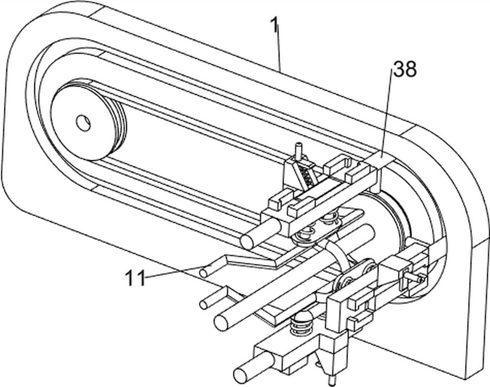
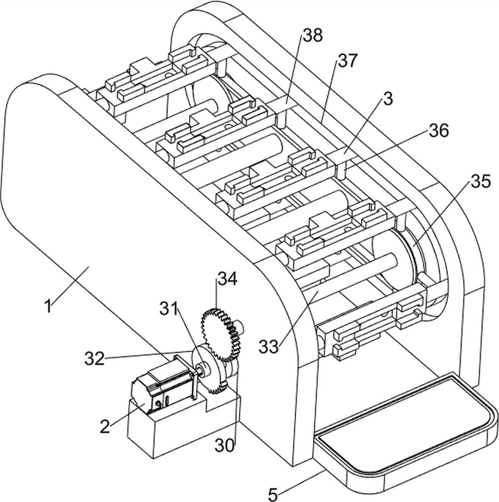
[0025] A utility knife mounting device such as Figure 1-5 As shown, it includes a mounting frame 1, a servo motor 2, a rotating mechanism 3, a pushing mechanism 4 and a sponge pad 5. The servo motor 2 is installed on the lower side of the left part of the mounting frame 1, and a rotating mechanism is connected between the left and right sides of the inner wall of the mounting frame 1. 3. A push mechanism 4 is provided in the middle of the upper left side of the mounting frame 1, and a sponge pad 5 is provided at the front of the mounting frame 1.

[0026] The rotating mechanism 3 includes a first bearing seat 30, a first rotating shaft 31, a missing gear 32, a second rotating shaft 33, a first full gear 34, a first belt transmission assembly 35, a connecting rod 36 and a placement plate 38. A first bearing seat 30 is provided in the front middle part of the left part, and the first bearing seat 30 is rotationally connected with a first rotating shaft 31 on the left side, and ...

Embodiment 2

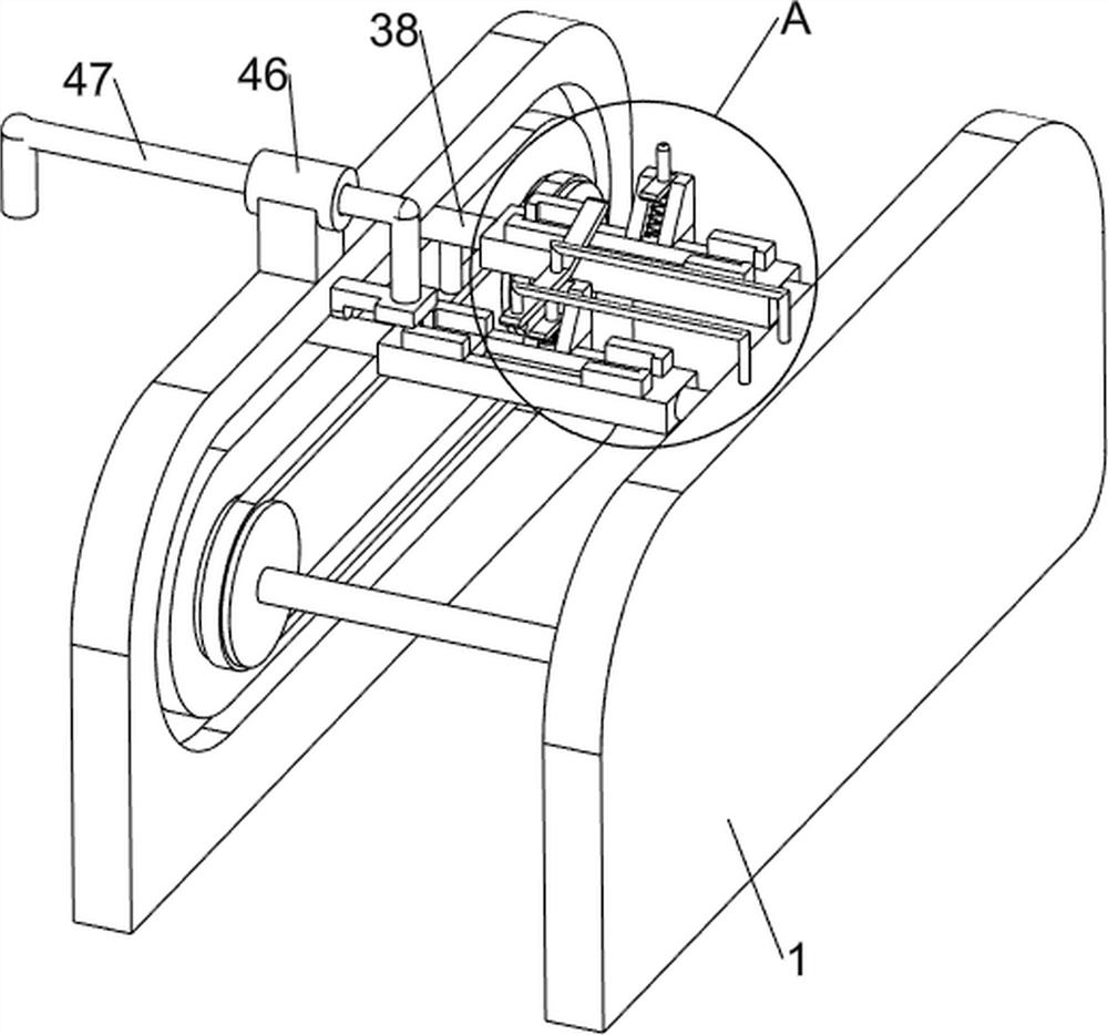
[0032] On the basis of Example 1, such as Figure 6-8 As shown, it also includes a containment block 6, a slide block 7, a first spring 8, a fixed rod 9 and a pressing plate 10, and the top of the right side of the installation frame 1 is provided with a fixed rod 9 facing the sliding sleeve 46, and the left end of the fixed rod 9 The bottom is provided with a pressing plate 10, and the middle of the right part of the placement plate 38 is provided with a containment block 6, and the front portion of the containment block 6 is slidably connected with a slider 7, and the bottom of the slide block 7 is connected with the middle of the right side of the top of the placement plate 38. spring 8.

[0033] Also include fixed mount 11, push block 13, push frame 14 and second spring 15, the left side inner wall front side of mounting frame 1 is provided with fixed mount 11, the middle part of placing plate 38 has groove 12, and the inner wall of support tube 45 A push block 13 is clampe...


PUM


Abstract

The invention relates to assembly mounting equipment, in particular to art knife mounting equipment. In order to solve the technical problem, the art knife mounting equipment is provided, which can automatically convey an art knife, fix the art knife, automatically mount an art knife assembly and automatically extrude out mounted art knives. The art knife mounting equipment comprises a mounting frame, a servo motor and a rotating mechanism, wherein the mounting frame is used for supporting the whole equipment; the servo motor is arranged on the lower side of the left portion of the mounting frame; and the rotating mechanism is arranged between the two sides of the inner wall of the mounting frame, and the rotating mechanism is connected with an output shaft of the servo motor. The effectsof automatically pushing the art knives to move forwards and automatically installing the art knives are achieved, when the art knives are installed, a sliding block presses the art knives on a containing plate, secondary fixing of the art knives is achieved, assembling of the art knives is completed, a fixing frame extrudes a pushing frame and the art knives upwards, and automatic extrusion of the art knives is achieved.

Description

technical field [0001] The invention relates to a component installation device, in particular to a utility knife installation device. Background technique [0002] A utility knife is a kind of knife used for art and handicrafts. It is mainly used to cut soft things. It is mostly composed of three parts: a plastic handle, a scabbard and a blade. It is a pull-out structure and comes in various sizes. [0003] When making a utility knife, the scabbard must first be embedded into the handle. The general utility knife installation method is that people insert the scabbard into the handle, fix the handle, and then use the impact part to install the scabbard into the knife. in the handle to complete the installation of the utility knife. However, due to the cumbersome operation steps during manual installation, people need to manually fix the knife handle on the right side of the impact part, which has a high potential safety hazard. People also need to remove the assembled utili...

Claims


Application Information

Patent Timeline
IPC IPC(8): B29C65/56B29C65/78B29L31/28
CPCB29C65/56B29C65/7841B29C65/7861B29L2031/28
Inventor 欧阳年香
Owner 欧阳年香
Why Eureka
Try Eureka