Supercharge Your Innovation With Domain-Expert AI Agents!

Inductor detection equipment

A technology for detection equipment and inductors, which is applied in the field of inductors, can solve the problems of the deviation of the efficiency of the conversion of sensor electric energy into magnetic energy, and the effect of affecting the detection effect.

Inactive Publication Date: 2021-02-23
山西泰妃尔商贸有限公司
View PDF0 Cites 0 Cited by
  • Summary
  • Abstract
  • Description
  • Claims
  • Application Information

AI Technical Summary

Problems solved by technology

[0003] Based on the discovery of the inventors above, the existing inductor detection equipment mainly has the following deficiencies, such as: when the inductor is detected, the probe needs to be inserted into the gap between the coils, if the probe only takes the coil One of the gaps is used for distance detection, and the other coil gaps are inconsistent with the detected coil gaps, which will affect the detection effect and lead to deviations in the efficiency of the sensor's conversion of electrical energy into magnetic energy.

Method used


Image

  • Inductor detection equipment
  • Inductor detection equipment
  • Inductor detection equipment

Examples


Embodiment 1

[0026] Example 1: Please refer to Figure 1-Figure 5 , the specific embodiments of the present invention are as follows:

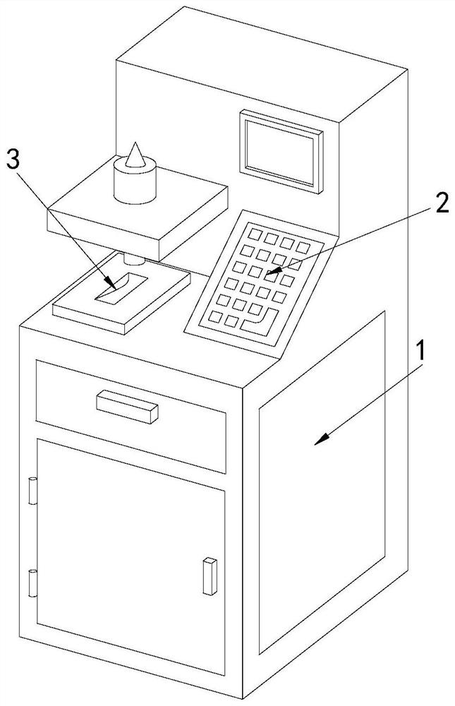
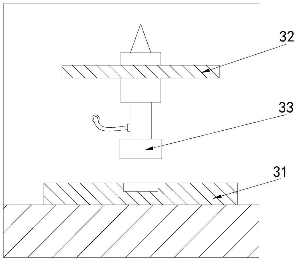
[0027] Its structure includes a main body 1, a control panel 2, and a workbench 3. The top of the main body 1 is provided with a control panel 2, and the workbench 3 is arranged on the top side of the main body 1. The workbench 3 includes a discharge plate 31 , a support plate 32, a detection device 33, the discharge plate 31 is fixed on the upper surface of the workbench 3, a detection device 33 is installed in the middle of the support plate 32, and the detection device 33 is installed vertically.

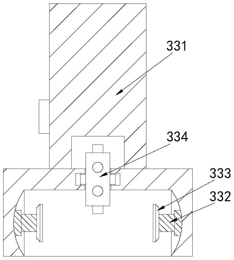
[0028] The detection device 33 includes a telescopic arm 331, a telescopic rod 332, a clamping head 333, and a detection wheel 334. The two ends of the bottom of the telescopic arm 331 are provided with a telescopic rod 332, and the end of the telescopic rod 332 is provided with a clamping head. 333, the end face of the clamping head 333 is circular, the det...

Embodiment 2

[0032] Example 2: Please refer to Figure 6-Figure 8 , the specific embodiments of the present invention are as follows:

[0033] The detection head a64 includes a movable groove b1, a detection piece b2, a tension spring b3, and a limit block b4, the movable groove b1 is arranged at the inner end of the detection head a64, two detection pieces b2 are provided, and Fitting inside the movable groove b1, the tension spring b3 connects the two detection pieces b2, the limit block b4 is arranged on the inner top of the two detection pieces b2, the tension spring b3 and the detection piece b2 The movable cooperation facilitates the expansion and contraction of the distance between the two detection pieces b2, so that the detection piece b2 can be easily inserted into the gap of the coil.

[0034] The detection piece b2 includes a detection body b21, a rubber block b22, a cavity b23, and a rubber pad b24. The bottom end of the detection body b21 is embedded with a rubber block b22,...


PUM


Abstract

Disclosed inductor detection equipment structurally comprises a main body, a control panel and a workbench, the control panel is arranged at the top of the main body, the workbench is arranged at theside end of the top of the main body, the workbench comprises a discharging plate, a supporting plate and a detection device, and the detection device comprises a telescopic arm, a telescopic rod, a clamping head and a detection wheel. The detection wheel comprises a rotating shaft, a conductive ring, a supporting rod, a mounting ring, a reset spring and a detection rod, and the detection rod comprises a conductive rod, a clamping groove, a contact piece and a detection head. The rotating shaft is used for driving the mounting ring to rotate, all gaps in the coil can be detected, and the detection rod in the mounting ring can rotate to detect all gaps in the coil. Therefore, the coil can be comprehensively detected, and the situation that after detection, the efficiency of converting electric energy of the inductor into magnetic energy deviates is avoided.

Description

technical field [0001] The invention relates to the field of inductors, in particular to an inductor detection device. Background technique [0002] An inductor is a component that can convert electrical energy into magnetic energy and store it. The detection equipment of the inductor mainly detects the winding distance of the coil in the inductor. If the distance between the coils is large, the efficiency of converting electrical energy into magnetic energy will be reduced, and the distance between the coils is relatively large. Smallness can increase the efficiency of converting electrical energy into magnetic energy, so the inductor needs to be tested after production. [0003] Based on the discovery of the inventors above, the existing inductor detection equipment mainly has the following deficiencies, such as: when the inductor is detected, the probe needs to be inserted into the gap between the coils, if the probe only takes the coil One of the gaps is used for distan...

Claims


Application Information

Patent Timeline
IPC IPC(8): G01R27/26
CPCG01R27/2611
Inventor 李达
Owner 山西泰妃尔商贸有限公司
Features
  • R&D
  • Intellectual Property
  • Life Sciences
  • Materials
  • Tech Scout
  • Unparalleled Data Quality
  • Higher Quality Content
  • 60% Fewer Hallucinations
Learn More