
Air conditioning control device, air conditioning control system, air conditioning control method and program

A technology of air conditioning and control systems, applied in heating and ventilation control systems, heating and ventilation safety systems, heating methods, etc., can solve problems such as inapplicable air conditioning

Active Publication Date: 2022-04-19
MITSUBISHI HEAVY IND THERMAL SYST
View PDF12 Cites 0 Cited by
  • Summary
  • Abstract
  • Description
  • Claims
  • Application Information

AI Technical Summary

Problems solved by technology

However, since the technique described in Patent Document 1 estimates the positions of all users in the room, it may not be suitable for providing air conditioning according to specific users.

Method used


Image

  • Air conditioning control device, air conditioning control system, air conditioning control method and program
  • Air conditioning control device, air conditioning control system, air conditioning control method and program
  • Air conditioning control device, air conditioning control system, air conditioning control method and program

Examples


no. 1 approach >

[0033] (The overall structure of the air conditioning control system)

[0034] Embodiments will be described in detail below with reference to the drawings.

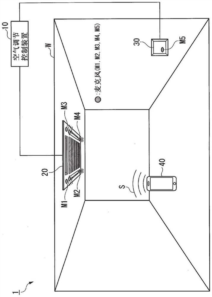
[0035] figure 1 It is a schematic diagram showing the overall configuration of the air-conditioning control system 1 of the first embodiment. It is assumed that the air-conditioning control system 1 of the first embodiment is used in an indoor space W where users exist, such as a library, a large store, a warehouse, or a factory. However, in other embodiments, the air-conditioning control system 1 is not limited to the usage as described above.

[0036] like figure 1 As shown, the air conditioning control system 1 of the first embodiment includes an air conditioning control device 10, an air conditioning indoor unit 20, a remote operation device 30, a terminal 40 held by a user, and microphones M1 to M5.

[0037] The air-conditioning control device 10 controls the air-conditioning indoor unit 20 so that the environme...

no. 2 approach >

[0116] Next, refer to Figure 7 The air-conditioning control system 1 of the second embodiment will be described.

[0117] Figure 7 It is a schematic diagram showing the overall configuration of the air-conditioning control system 1 of the second embodiment.

[0118] like Figure 7 As shown, the air-conditioning control system 1 of the second embodiment includes an air-conditioning indoor unit 21 different from the air-conditioning indoor unit 20 . The indoor unit 21 for air conditioning is configured similarly to the indoor unit 20 for air conditioning, and four microphones M5 to M7 (second ultrasonic sensors) are provided in the indoor unit 21 for air conditioning.

[0119] That is, the air-conditioning control system 1 of the second embodiment is identical to the second ultrasonic sensor at the point where another air-conditioning indoor unit 21 is included and at the point where the second ultrasonic sensor is not provided at the remote operation device 30 but is provi...


PUM


Abstract

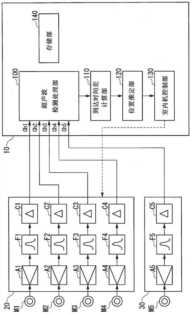
An air-conditioning control device that controls an air-conditioning indoor unit based on the terminal position of a terminal held by a user includes an ultrasonic detection processing unit configured by a first ultrasonic sensor provided on the above-mentioned air-conditioning indoor unit and a device connected to the air-conditioning The second ultrasonic sensor at a different position of the indoor unit is used for adjustment to detect the ultrasonic wave emitted from the terminal; the arrival time difference calculation unit compares the time when the ultrasonic wave is detected by the first ultrasonic sensor The arrival time difference is calculated as the time difference to the ultrasonic wave; the position estimating unit estimates the terminal position of the terminal based on the arrival time difference; and the indoor unit control unit controls the air conditioning indoor unit based on the terminal position.

Description

technical field [0001] The present invention relates to an air conditioning control device, an air conditioning control system, an air conditioning control method and a program. [0002] This application claims priority based on Japanese Patent Application No. 2018-093758 filed on May 15, 2018, the contents of which are incorporated herein. Background technique [0003] When an air-conditioning indoor unit such as an air conditioner provides air conditioning according to a user in a room, it is necessary to grasp the position of the user. For example, Patent Document 1 discloses a technique for estimating a user's position by detecting an indoor temperature distribution. However, since the technique described in Patent Document 1 estimates the positions of all users in the room, it may not be suitable for providing air conditioning for specific users. [0004] On the other hand, there is known a technique for estimating a user's position using a position estimating method ...

Claims


Application Information

Patent Timeline
Patent Type & Authority Patents(China)
IPC IPC(8): F24F11/59F24F11/46F24F11/56F24F11/64F24F11/89
CPCF24F11/59F24F11/56F24F11/48F24F2120/12
Inventor 水野尚夫近藤成治西川尚希丸山真范樱井贵夫清水健志岩田久雄小野川英
Owner MITSUBISHI HEAVY IND THERMAL SYST
Learn More