Particle detection device

A detection device and particle technology, which is applied in the direction of measuring device, particle size analysis, particle suspension analysis, etc., can solve the problems of increased error and large proportion of impedance change, and achieve the effect of suppressing resistance change, suppressing impedance, and accurate particle amount

Active Publication Date: 2014-05-14
TOYOTA JIDOSHA KK
View PDF5 Cites 0 Cited by
  • Summary
  • Abstract
  • Description
  • Claims
  • Application Information

AI Technical Summary

Problems solved by technology

Furthermore, when the deterioration of the electrodes and the like is severe, the proportion of the change due to the deterioration of the electrodes and the like is large among the detected changes in impedance.
In this case, it is considered that the error between the amount of particles calculated from the amount of impedance change and the actual amount of particles increases.

Method used


Image

  • Particle detection device
  • Particle detection device
  • Particle detection device

Examples


Embodiment approach 1

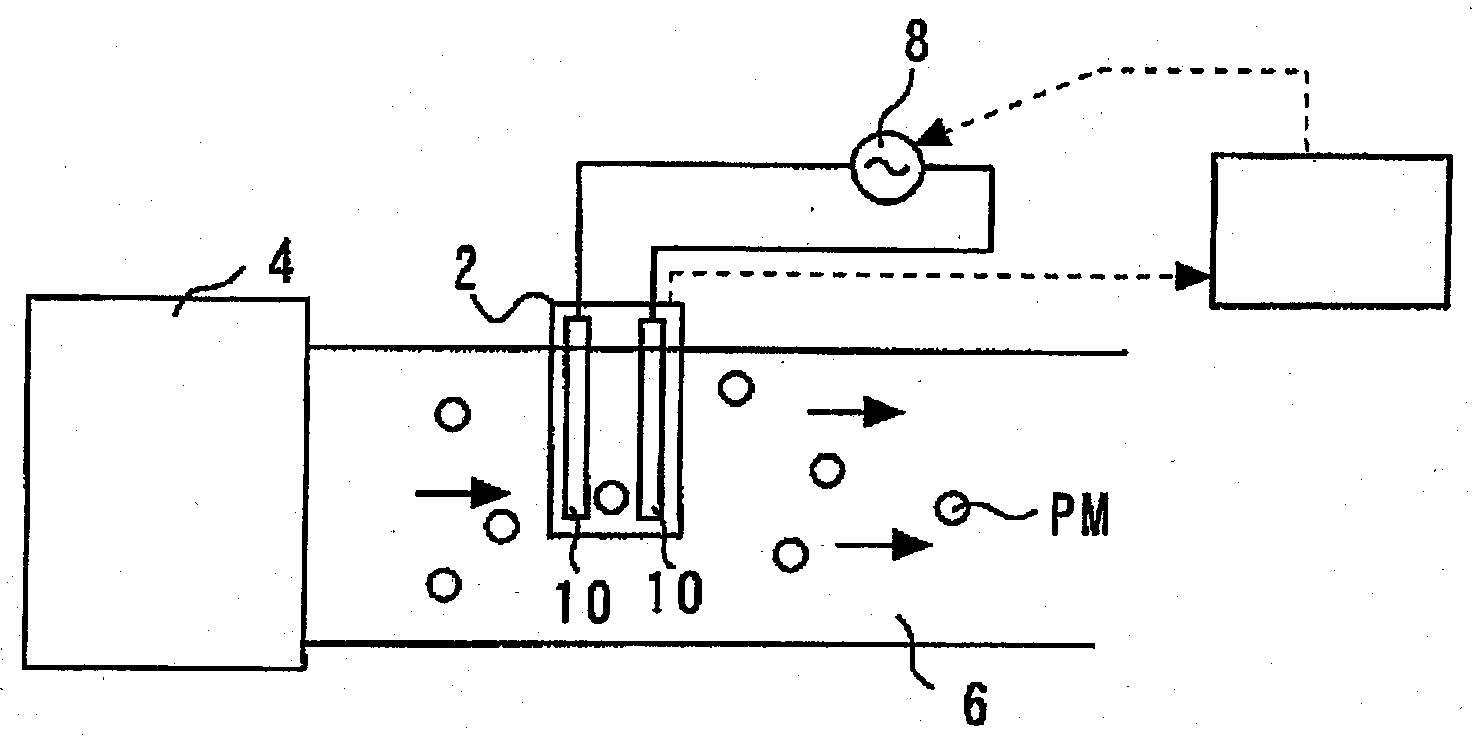
[0046] figure 1 It is a schematic diagram for explaining the installation state of the PM sensor according to Embodiment 1 of the present invention. Such as figure 1 As shown, the PM sensor 2 is provided, for example, in an exhaust path 6 of an internal combustion engine 4 mounted on a vehicle or the like. An AC power source 8 for applying AC and DC voltages is connected to the PM sensor 2 (particle detection device). The PM sensor 2 has a pair of electrodes 10 arranged separately. At least a part of the electrode 10 is provided in the exhaust path 6 in a state capable of contacting the exhaust gas. In addition, although illustration is omitted, the PM sensor 2 is connected to an impedance detector that detects impedance between the electrodes 10 , a frequency detector that detects an AC frequency, and the like.

[0047] The system has a control device 12 . The control device 12 is connected to various detectors of the PM sensor 2 and the AC power supply 8 . The control ...

Embodiment approach 2

[0090] The system of Embodiment 2 is the same as the system of Embodiment 1 except that the timing for calculating the number of PM particles is specified. Figure 8 It is a diagram for explaining the PM accumulation amount and aging of the PM sensor 2 . exist Figure 8 In , the horizontal axis represents time, and the vertical axis represents PM accumulation amount.

[0091] Such as Figure 8 As shown in FIG. 2 , the PM accumulation amount on the PM sensor 2 increases with time, but once it reaches a saturated state, it stops increasing and becomes constant. In addition, since the resistance of the PM sensor 2 changes according to the amount of PM accumulation, when it is in a saturated state and the amount of PM accumulation is constant, the resistance does not change but becomes constant.

[0092] In the second embodiment, when the actual resistance Rm of the PM sensor 2 becomes a resistance indicating a saturated state, an AC voltage obtained by continuously changing th...


PUM


Abstract

Disclosed is a particulate matter detection device that detects the diameter and the amount of particulates in exhaust gas while reducing detection error caused by deterioration such as the deterioration of electrodes. In the particulate matter detection device, which measures particulates in a gaseous body, AC voltages having different frequencies are applied to a pair of electrodes disposed apart from each other. The resulting impedances to the different frequencies are detected. A resistance component and / or a capacitance component of the impedances to the different frequencies are calculated. The average diameter and / or the number of particulates in the gaseous body are estimated in accordance with changes in the resistance component and / or the capacitance component.

Description

technical field [0001] The present invention relates to particle detection devices. In particular, it relates to a particle detection device arranged in an exhaust path of an internal combustion engine and suitable for detecting particles in exhaust gas. Background technique [0002] Conventionally, as described in Patent Document 1, a particle sensor for detecting the amount of particles in exhaust gas of an internal combustion engine has been disclosed. Such a sensor includes electrodes arranged in parallel with a space therebetween. The sensor is arranged on the exhaust path in such a way that at least part of the electrodes are exposed to the exhaust gas. As the exhaust gas flows through the exhaust path, particulates in the exhaust gas build up on the electrodes. As a result, the impedance between electrodes changes. The sensor of Patent Document 1 detects such a change in impedance, and thereby detects the amount of fine particles accumulated between electrodes. ...

Claims


Application Information

Patent Timeline
Patent Type & Authority Patents(China)
IPC IPC(8): G01N27/02G01N15/02G01N15/06
CPCG01N2015/0277G01N15/0656G01N15/0606G01N15/0266
Inventor 青木圭一郎
Owner TOYOTA JIDOSHA KK
Why Eureka
Try Eureka