Eureka AIR delivers breakthrough ideas for toughest innovation challenges, trusted by R&D personnel around the world.

Quantitative fertilizing machine

A technology of quantitative fertilization and quantifier, which is applied in the direction of fertilization device, fertilizer distributor, application, etc., to achieve the effect of ensuring the amount of fertilizer, uniform texture and avoiding waste

Inactive Publication Date: 2021-02-26
曲靖市马龙区品康农业科技有限公司
View PDF0 Cites 0 Cited by
  • Summary
  • Abstract
  • Description
  • Claims
  • Application Information

AI Technical Summary

Problems solved by technology

[0005] In order to overcome the problems in the background technology, the present invention provides a quantitative fertilizer applicator that can filter out impurities and agglomerated fertilizers in the fertilizer, which is beneficial to the uniform texture of the fertilizer; through the quantitative application of fertilizers, excessive fertilizers can be intercepted to prevent fertilizers from waste, avoiding the harm caused by excessive application to crops, preventing crop malnutrition caused by insufficient application, and achieving scientific fertilization; the invention can also store the filtered and quantitative fertilizer to facilitate the continuity of the fertilization process and improve the efficiency of fertilization. Efficiency; the free adjustment of the angle of the fertilization pipe is convenient for fertilization in different directions; the number of fertilization pipes can be increased or decreased as needed, which is conducive to satisfying multiple lines of fertilization and improving efficiency; the horizontal movement of the fertilization device can be realized, saving time and effort

Method used


Image

  • Quantitative fertilizing machine
  • Quantitative fertilizing machine

Examples


Embodiment Construction

[0019]In order to make the objectives, technical solutions, and beneficial effects of the present invention clearer, the preferred embodiments of the present invention will be described in detail below with reference to the accompanying drawings, so as to facilitate the understanding of the skilled person.

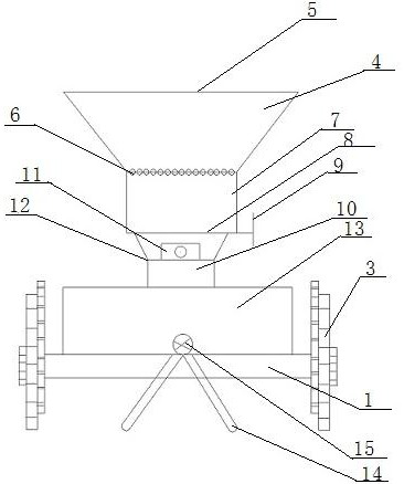
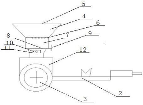
[0020]Such asfigure 1 As shown, the quantitative fertilizer applicator includes a fertilizer applicator and a supporting device; wherein, the fertilizer applicator includes a fertilizer box 4, a fertilizer box cover 5, a filter screen 6, a filter box 7, a baffle plate 8, a feeding tube 10, Storage box 13, fertilizer pipe 14; fertilizer box cover 5 is provided on the top of fertilizer box 4, fertilizer box cover 5 is matched with fertilizer box 4, fertilizer box 4 is provided with filter screen 6 at the bottom, filter box 7 is set on filter screen 6 Below, the bottom of the filter box 7 is provided with a baffle plate 8, and the bottom of the filter box 7 is provided with a feeding ...


PUM


Abstract

The invention belongs to the field of agricultural fertilizing instruments, and particularly relates to a quantitative fertilizing machine. The quantitative fertilizing machine comprises a fertilizingdevice and a supporting device, wherein the fertilizing device comprises a fertilizer box, a fertilizer box cover, a filter sieve, a filter material box, a striker plate, a discharging pipe, a storage box and a fertilizing pipe; the fertilizer box cover is arranged at the top of the fertilizer box and matched with the fertilizer box, the filter sieve is arranged at the bottom of the fertilizer box, the filter material box is arranged below the filter sieve, the striker plate is arranged at the bottom of the filter material box, the discharging pipe is arranged below the filter material box, afertilizer batcher is arranged on the outer wall of the discharging pipe, and the other end of the discharging pipe is connected with the storage box; and the fertilizing pipe is arranged at the bottom of the storage box, and a switch for controlling a discharge port is arranged at the outer side of the storage box. The filter sieve can ensure uniform texture of the applied fertilizer; the striker plate and an intercepting plate can intercept excessive fertilizer in time; the fertilizer batcher can ensure scientific fertilization; the storage box can ensure the continuity of the fertilizationprocess; and the fertilizing pipe can ensure fertilization in different directions.

Description

Technical field:[0001]The invention relates to a quantitative fertilizer applicator, which belongs to the field of agricultural equipment.Background technique:[0002]In the process of farming, chemical fertilizers must be spread before sowing the arable land. With the implementation of reform and opening up, most of the young and middle-aged laborers in rural areas go out to work, leaving the elderly or women to work at home. The labor force is weak; especially in mountainous and hilly areas, the complex The geographical structure makes it inconvenient to use large-scale machinery. Therefore, the spreading of chemical fertilizers is usually done manually, which is labor intensive and low in work efficiency.[0003]In order to increase the yield of crops, it is sometimes necessary to sow multiple fertilizers at the same time. For manual sowing, it is necessary to mix the fertilizers and then sow or sow different types of fertilizers in batches, which is time-consuming and laborious, eve...

Claims


Application Information

Patent Timeline
Patent Type & Authority Applications(China)
IPC IPC(8): A01C15/12A01C15/00
CPCA01C15/00A01C15/12
Inventor 张建党
Owner 曲靖市马龙区品康农业科技有限公司
Why Eureka
Eureka Blog
Learn More