Purging device for valve production

A technology of cleaning and blowing, which is applied to the cleaning methods, cleaning methods and utensils, chemical instruments and methods using gas flow, etc., can solve the problems of low work efficiency, poor cleaning effect, unfavorable enterprise development, etc., to improve work efficiency. , the effect of saving time

Pending Publication Date: 2021-02-26
HUNAN ANFU ENGINE VALVE
View PDF0 Cites 0 Cited by
  • Summary
  • Abstract
  • Description
  • Claims
  • Application Information

AI Technical Summary

Problems solved by technology

[0006] The purpose of the invention is to provide a cleaning and blowing device for valve production, which solves the problem of manual cleaning and cooling of the valve during the production process of the valve, which not only has low work efficiency and poor cleaning effect, but also increases labor costs, which is not conducive to enterprises. the problem of development

Method used


Image

  • Purging device for valve production
  • Purging device for valve production

Examples


Embodiment 1

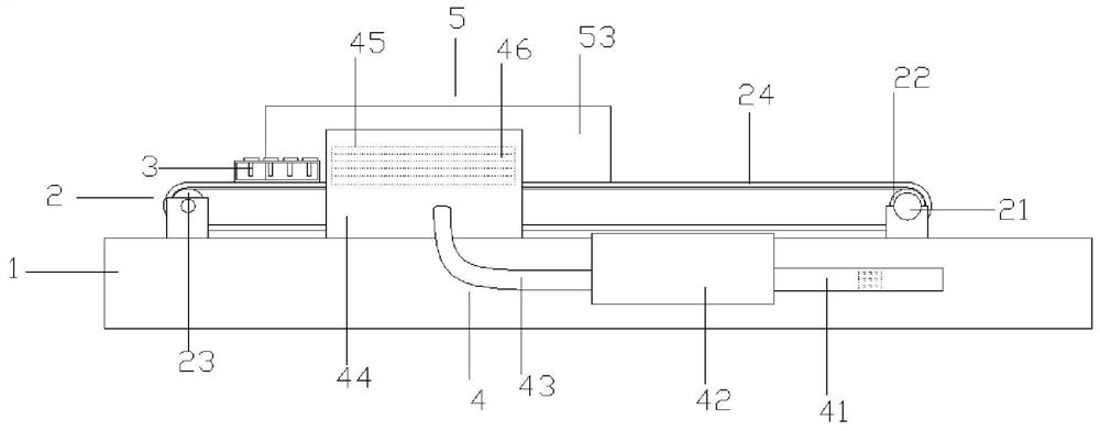
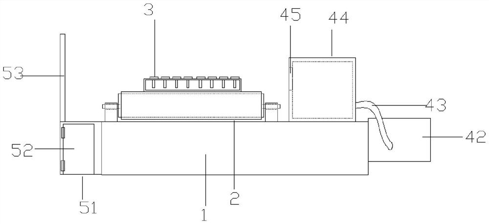
[0024] Figure 1-Figure 2 Shown is a cleaning and blowing device for valve production, the cleaning and blowing device includes a production rack 1, a transfer structure 2 placed on the production rack 1, a valve 3 placed on the transfer structure 2, placed on the production rack 1 Rack 1 and the cleaning and blowing structure 4 arranged along the direction of the conveying structure 2, the dust collecting structure 5 placed on the production rack 1 and arranged along the direction of the conveying structure 2, the cleaning and blowing structure 4 and the collecting The dust structure 5 is relatively arranged,

[0025] The output end of the cleaning and blowing structure 4 is higher than the conveying structure 2 and matches the height of the air valve 3 , and the top of the dust collecting structure 5 is higher than the cleaning and blowing structure 4 .

[0026] The transmission structure 2 includes a drive motor 21 placed on the upper end side of the production frame 1 and...


PUM


Abstract

The invention discloses a purging device for valve production, which comprises a production frame, a conveying structure arranged on the production frame, a valve arranged on the conveying structure,a purging structure arranged on the production frame and arranged along the direction of the conveying structure, and a dust collection structure arranged on the production frame and arranged along the direction of the conveying structure, wherein the purging structure and the dust collection structure are arranged oppositely, the output end of the purging structure is higher than the conveying structure and highly matched with the valve, and the top end of the dust collection structure is higher than the purging structure. During use of the purging device, a workpiece is placed on a conveyingbelt, the workpiece is moved through the conveying structure, when the workpiece passes through the purging structure, an exhaust fan sucks air into an air guide box through an air inlet pipe and anair guide pipe, then the air is exhausted through an air outlet to purge the workpiece, impurities such as dust are collected by the dust collection structure, and meanwhile the cooling effect is achieved; and therefore, the trouble of manual cleaning is avoided, time is saved, working efficiency is improved, and long-term development of enterprises is facilitated.

Description

technical field [0001] The invention relates to the technical field of cleaning and blowing for valve generation, in particular to a cleaning and blowing device for valve production. Background technique [0002] The valve is an important part of the engine. The function of the valve is to be responsible for inputting air into the engine and discharging the exhaust gas after combustion. From the structure of the engine, it is divided into intake valve and exhaust valve. The role of the intake valve is to draw air into the engine and mix it with fuel for combustion; the role of the exhaust valve is to discharge the burned exhaust gas and dissipate heat. [0003] Its function is to input fuel into the engine and discharge exhaust gas. The traditional engine has only one intake valve and one exhaust valve per cylinder. This design structure is relatively simple, the cost is low, the maintenance is convenient, and the low-speed performance is better. Disadvantages It is diffi...

Claims


Application Information

Patent Timeline
IPC IPC(8): B08B5/02B08B13/00
CPCB08B5/023B08B13/00
Inventor 黄昊郑家宏全必共
Owner HUNAN ANFU ENGINE VALVE
Why Eureka
Try Eureka