Supercharge Your Innovation With Domain-Expert AI Agents!

A cross-shaped workpiece assembly and welding device

A welding device and cross-shaped technology, applied in welding equipment, auxiliary devices, auxiliary welding equipment, etc., can solve the problems of difficult deformation control and difficult clamping of cross-shaped workpieces for welding.

Active Publication Date: 2022-06-17
NUCLEAR POWER INSTITUTE OF CHINA
View PDF19 Cites 0 Cited by
  • Summary
  • Abstract
  • Description
  • Claims
  • Application Information

AI Technical Summary

Problems solved by technology

[0003] The technical problem to be solved by the present invention is: the welding of cross-shaped workpieces is not easy to be clamped, and the deformation control in the welding process is difficult. High-precision assembly of a cross-shaped workpiece, and can control the deformation of the cross-shaped workpiece during welding and forming

Method used


Image

  • A cross-shaped workpiece assembly and welding device
  • A cross-shaped workpiece assembly and welding device
  • A cross-shaped workpiece assembly and welding device

Examples


Embodiment 1

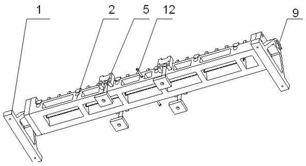
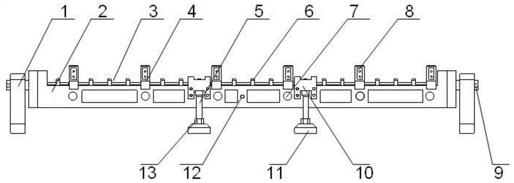
[0038] This embodiment provides a cross-shaped workpiece assembly and welding device, including a mounting base 2 and a support 1, the mounting base 2 is mounted on the support 1, the mounting base 2 is a cuboid frame structure, and the mounting base 1 is placed on the support 1 through the support 1. on the workbench or on the workshop floor.

[0039] The upper surface of the installation base 2 is provided with a through groove, the length of the through groove extends in the same direction as the length of the installation base 2, and the through groove runs through the installation base 2 along the height direction of the installation base 2; the through groove is used to install the cross-shaped workpiece to be welded , a plurality of cross-shaped workpieces to be welded can be arranged at intervals in the through groove along the length direction of the mounting base 2 .

[0040] The side surface of the mounting base 2 is provided with a plurality of threaded holes, and ...

Embodiment 2

[0045] On the basis of Embodiment 1, it is further improved, and further includes a plurality of key press bars 6 and pressing bolts 14, and the long axis direction of each key press bar 6 is in the same direction as the width direction of the through groove; the upper surface of the mounting base 2 is provided with A plurality of threaded holes, through holes are provided on the key press bar 6; after the pressing bolt 14 passes through the through hole on the key press bar 6, the thread is threaded with the threaded hole on the installation base 2, and the key press strip 6 is fixed on the installation base. 2. The upper surface; the pressing plate 3 is pressed between the lower surface of the key bead 6 and the upper surface of the mounting base 2. Further preferably, a plurality of through holes are provided on the key bead 6, and the plurality of through holes are evenly distributed along the axial direction of the key bead 6; near the side.

Embodiment 3

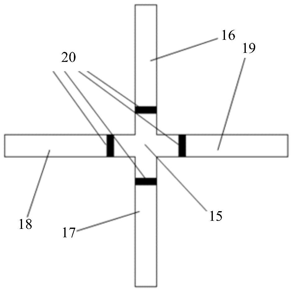
[0047] Further improvement is made on the basis of Embodiment 2. Each bridge-shaped stopper 4 is an L-shaped plate, and the free end of the vertical plate of the L-shaped plate is fixed on the upper surface of the mounting base 2, and the free end of the horizontal plate of the L-shaped plate is free. The end faces another bridge-shaped limiting member 4 in the same group, and the two L-shaped plates are symmetrically distributed in a bridge-shaped structure; the vertical plate of each L-shaped plate is also provided with a pressing member 8; the pressing member 8 is used for The upper wing plate 16 in the cruciform workpiece to be welded is pressed. The pressing member 8 is a plate-like structure, and the pressing member 8 is fixed on the vertical plate of the L-shaped plate by bolts. At this time, the pressing member 8 preferably adopts bolts. After the bolts on both sides penetrate the vertical plate of the L-shaped plate, the bolts The ends of the upper wing plate 16 abut ...


PUM


Abstract

The invention discloses a cross-shaped workpiece assembly and welding device, which includes a mounting base and a support. A vertical through groove is formed on the upper surface of the mounting base. The length extension direction of the through groove is in the same direction as the length direction of the mounting base. The installation base runs through the installation base along the height direction; there are several threaded holes on the side of the installation base, the axis direction of the threaded holes is perpendicular to the height direction of the installation base, and the threaded holes are connected with the through groove; the threaded holes are screwed with jacking bolts ;The upper surface of the installation base is located on both sides of the width direction of the through groove and can be detachably installed with pressure plates; the upper surface of the installation base is provided with several groups of bridge components, each group of bridge components includes two bridge-shaped limiters, two The bridge-shaped limiting parts are symmetrically distributed on both sides in the width direction of the through groove, and are disconnected above the through groove; each bridge-shaped limiting part is provided with a pressing piece. The device of the invention can realize the high-precision assembly of a cross-shaped workpiece, and can control the deformation of the cross-shaped workpiece during welding and forming.

Description

technical field [0001] The invention relates to the technical field of machining, in particular to a cross-shaped workpiece assembly and welding device. Background technique [0002] The cross-shaped control rod is manufactured by welding structure, and its assembly and molding method is the butt welding of the central small cross piece and the four-wing plate. Welds are arranged around the structure. It is not easy to choose the clamping method of the inner small cross-shaped piece, and the clamping device is not easy to arrange. For the cross-shaped workpiece with thicker wings, it needs to be completed by double-sided welding, and the welding deformation of the structure is difficult to control. larger. For the forming of the cross-shaped workpiece with this structure, in order to ensure the shape characteristics of the cross-shaped workpiece, in the assembly process, the precise positioning of each wing plate and the cross block needs to be realized by the tooling. The...

Claims


Application Information

Patent Timeline
Patent Type & Authority Patents(China)
IPC IPC(8): B23K37/00B23K37/04B23K37/047
CPCB23K37/00B23K37/0443B23K37/047
Inventor 魏连峰唐彬王世忠王军陈高詹蒲永兴陈勇
Owner NUCLEAR POWER INSTITUTE OF CHINA
Features
  • R&D
  • Intellectual Property
  • Life Sciences
  • Materials
  • Tech Scout
  • Unparalleled Data Quality
  • Higher Quality Content
  • 60% Fewer Hallucinations
Learn More