Hydraulic compound valve based on sequential pressure reduction overflow function

A compound valve and function technology, applied in the direction of fluid pressure actuating devices, servo motor components, mechanical equipment, etc., can solve the problems of use, installation and maintenance, etc., achieve a small number of parts, and realize the function and structure of sequential decompression and overflow. compact effect

Pending Publication Date: 2021-02-26
SAIKESI HYDRAULIC TECH CO LTD
View PDF0 Cites 1 Cited by
  • Summary
  • Abstract
  • Description
  • Claims
  • Application Information

AI Technical Summary

Problems solved by technology

Often, many densely packed cartridge valves are arranged on the valve body, which brings troubles to use, installation and subsequent maintenance

Method used


Image

  • Hydraulic compound valve based on sequential pressure reduction overflow function
  • Hydraulic compound valve based on sequential pressure reduction overflow function
  • Hydraulic compound valve based on sequential pressure reduction overflow function

Examples


Embodiment Construction

[0023] Embodiments of the present invention will be further described in detail below in conjunction with the accompanying drawings.

[0024] Figures 1 to 7 It is a schematic diagram of the structure and principle of the present invention.

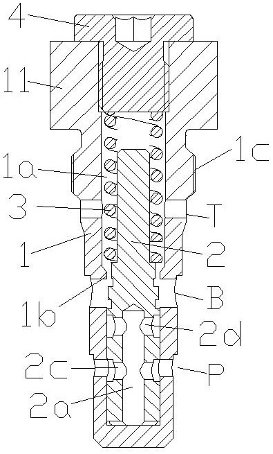
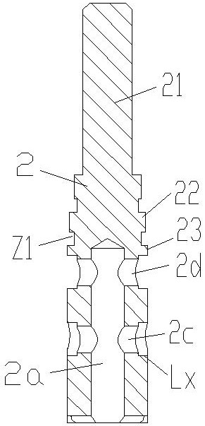
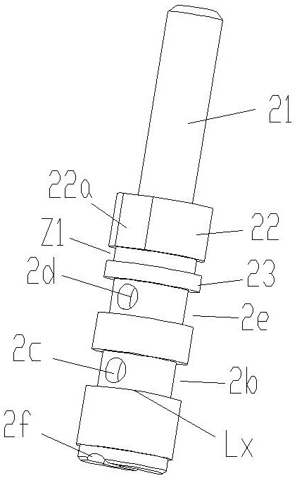
[0025] The reference signs are: action surface S, sealing ring M, damping channel Z, annular damping groove Z1, throttling area Ax, control edge Lx, mouth edge Lt, valve sleeve 1, valve cavity 1a, inner shoulder 1b, External thread 1c, positioning boss 11, valve core 2, central oil passage 2a, annular control groove 2b, pressure oil port 2c, connecting oil hole 2d, annular connecting groove 2e, bottom groove 2f, spring guide rod section 21, upper stage Shoulder 22, longitudinal section 22a, lower shoulder 23, pressure spring 3, pressure regulating screw plug 4, mounting part 5.

[0026] As shown in the figure, the present invention discloses a hydraulic composite valve based on the function of sequential decompression and overflow. The ...


PUM


Abstract

The invention discloses a hydraulic compound valve based on a sequential pressure reduction overflow function. The hydraulic compound valve comprises a valve sleeve, a valve core and a pressure spring, wherein a valve cavity is formed in the valve sleeve, a high-pressure oil port P, a secondary pressure port B and an oil return port T are formed in the valve sleeve, a center oil way is formed in the bottom surface of the valve core, an annular control groove is machined in the circumferential face of the valve core, a pressure oil port used for communicating the port P and the center oil way in the radial direction is formed in the annular control groove, a connecting oil hole used for communicating the center oil way and the port B after the valve core moves upwards is further machined inthe valve core, a control edge of the annular control groove and an opening edge of the port P form a throttling area for realizing the pressure reduction function of the valve when the valve core moves upwards, an upper shoulder with longitudinal sections on two sides and a lower shoulder positioned below the upper shoulder are formed on the valve core, when the valve core is in an original state, the port B communicates with the port T, and the longitudinal sections is matched with an inner shoulder of the valve sleeve when the valve core moves upwards to form a damping channel capable of enabling a part of oil of the port B to be shunted back to the port T to achieve the overflow function of the valve.

Description

technical field [0001] The invention relates to the technical field of hydraulic control, in particular to a hydraulic valve with composite function, in particular to a hydraulic composite valve based on sequential decompression and overflow function. Background technique [0002] Hydraulic valves are widely used in hydraulic equipment and hydraulic components. Hydraulic valves are divided into plate type, pipe type and cartridge type. Due to the limitation of the space structure of equipment and components, cartridge hydraulic valves have been widely used in compact hydraulic components. Especially in the hydraulic rotary motor, it is widely used because of its small size, convenient installation and great space saving. But at present, most rotary motors have an independent cartridge valve corresponding to one function, so there will be higher requirements on the space design of the plug-in body. Often, many densely packed cartridge valves are arranged on the valve body, ...

Claims


Application Information

Patent Timeline
Patent Type & Authority Applications(China)
IPC IPC(8): F15B13/02
CPCF15B13/024F15B13/025F15B2013/004F15B2013/006
Inventor 徐建江姚广山李禧高魏磊
Owner SAIKESI HYDRAULIC TECH CO LTD
Why Eureka
Try Eureka