
Pipe built-in combined type pressure reducing valve

A combined, pressure-reducing valve technology, applied in the field of pressure-reducing valves, can solve the problems of complex structure, difficult disassembly and replacement, large size, etc. Effect

Active Publication Date: 2015-05-20
优布劳(中国)精酿啤酒有限公司
View PDF6 Cites 0 Cited by
  • Summary
  • Abstract
  • Description
  • Claims
  • Application Information

AI Technical Summary

Problems solved by technology

[0004] The purpose of the present invention is to provide a combined pressure reducing valve with a built-in pipeline to solve the problems of existing pressure reducing valves with complex structure, large size, or difficulty in disassembly and replacement.

Method used


Image

  • Pipe built-in combined type pressure reducing valve
  • Pipe built-in combined type pressure reducing valve
  • Pipe built-in combined type pressure reducing valve

Examples


Embodiment Construction

[0017] The present invention will be further described in detail below in conjunction with the accompanying drawings and specific embodiments.

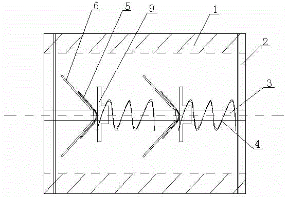
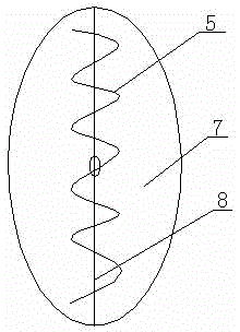
[0018] see Figure 1 to Figure 2 , a combined pressure reducing valve built in a pipeline, comprising a cylindrical valve body 1, a guide rod 3 and two or more sets of pressure reducing components. The guide rod 3 is arranged along the axis of the valve body 1, and the guide rod 3 is fixed on the valve body 1 by positioning pins 2 at both ends thereof. The decompression assembly includes a valve disc set 6, a torsion spring 5 and a return spring 4 which are sequentially nested on the guide rod 3. The valve disc set 6 is hinged by two semicircular valve discs 7. As a result, the opening of the valve disc group 6 faces the inlet end of the valve body 1, and the torsion spring 5 is attached to the back of the valve disc group 6; specifically, the central opening of the valve disc group 6 is sleeved on the guide rod 3, and the torsion T...


PUM


Abstract

The invention discloses a pipe built-in combined type pressure reducing valve. The pipe built-in combined type pressure reducing valve comprises a cylindrical valve body (1), a guide rod (3) and two or more pressure reduction assemblies. The guide rod (3) is arranged along the axis of the valve body (1) and fixed to the valve body (1) through positioning pins (2) at the two ends of the guide rod (3). Each pressure reduction assembly comprises a valve clack set (6), a torsion spring (5) and a reset spring (4), wherein the valve clack set (6), the torsion spring (5) and the reset spring (4) are sequentially inlaid on the guide rod (3) in a sleeving mode. Each valve clack set (6) is formed by connecting two semicircular valve clacks (7) in a hinge mode, an opening of each valve clack set (6) faces the inlet end of the valve body (1), each torsion spring (5) is attached to the back of the corresponding valve clack set (6), and the two or more pressure reduction assemblies are sequentially installed on the guide rod (3) in the direction from the inlet end to the outlet end of the valve body (1). The structure is simple, installation is convenient, and the pressure reduction function is achieved.

Description

technical field [0001] The invention relates to a pressure reducing valve, in particular to a pipeline built-in combined pressure reducing valve. Background technique [0002] The pressure reducing valve is a valve that reduces the inlet pressure to a certain required outlet pressure by adjusting, and relies on the energy of the medium itself to automatically maintain the outlet pressure. The pressure reducing valve is a widely used valve, which is used in various pipe networks to ensure that the medium enters from the high pressure end of the pressure reducing valve to the low pressure end, and the outflow medium can meet our design requirements. [0003] At present, the existing pressure reducing valves are mainly membrane type and inner spring piston type. These two types of pressure reducing valves have complex structures and large sizes. They are connected to pipelines through flanges or screws during installation. The fixed flange hole is limited, and the construction...

Claims


Application Information

Patent Timeline
Patent Type & Authority Applications(China)
IPC IPC(8): F16K17/20
CPCF16K17/30F16K47/04
Inventor 高邵秋泓高凯旋
Owner 优布劳(中国)精酿啤酒有限公司
Learn More