Pressure reducing mechanism

A technology of decompression mechanism and decompression pin, which is applied in the direction of mechanical equipment, engine components, machines/engines, etc., can solve problems such as difficulty in assembling the decompression structure, and achieve the effect of simple structure, meeting the needs of use, and simple operation

Active Publication Date: 2022-04-12
ZHEJIANG QIANJIANG MOTORCYCLE
View PDF8 Cites 0 Cited by
  • Summary
  • Abstract
  • Description
  • Claims
  • Application Information

AI Technical Summary

Problems solved by technology

[0005] The purpose of the present invention is to propose a decompression mechanism for the above-mentioned problems existing in the prior art, which solves the problem of difficult assembly of the existing decompression structure

Method used


Image

  • Pressure reducing mechanism
  • Pressure reducing mechanism
  • Pressure reducing mechanism

Examples


Embodiment Construction

[0022] The following are specific embodiments of the present invention and in conjunction with the accompanying drawings, the technical solutions of the present invention are further described, but the present invention is not limited to these embodiments.

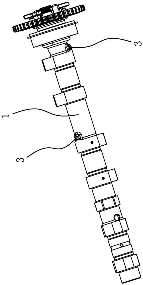
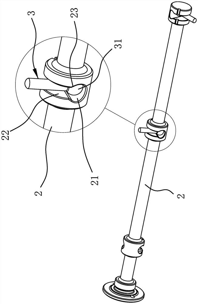
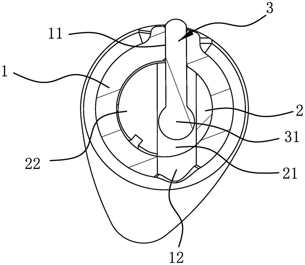
[0023] Such as figure 1 and figure 2 As shown, the decompression mechanism includes a hollow camshaft 1, a decompression shaft 2 coaxially penetrated in the camshaft 1, and a round bar-shaped decompression pin 3 arranged perpendicular to the axis of the decompression shaft 2. The opposite sides of the camshaft 1 are respectively provided with a pressure reducing hole 11 and a through hole 12 , and the outer end of the pressure reducing pin 3 is penetrated in the pressure reducing hole 11 and can protrude from the outer surface of the camshaft 1 .

[0024] Wherein, the decompression shaft 2 has a cylindrical installation part corresponding to the position of the decompression hole 11, the installation part is coaxially ar...


PUM


Abstract

The invention provides a pressure reducing mechanism, and belongs to the technical field of engines. The problem that an existing pressure reduction structure is difficult to assemble is solved. The pressure reducing mechanism is arranged at a hollow cam shaft, a pressure reducing hole is formed in the side portion of the cam shaft in a penetrating mode, the pressure reducing mechanism comprises a pressure reducing shaft arranged in the cam shaft in a penetrating mode and a rod-shaped pressure reducing pin, the pressure reducing pin is perpendicular to the pressure reducing shaft, and the outer end of the pressure reducing pin is arranged in the pressure reducing hole in a penetrating mode. A limiting hole is formed in the position, deviating from the center, in the pressure reducing shaft in the direction perpendicular to the axis in a penetrating mode, a through hole is formed in the other side, opposite to the pressure reducing hole, of the cam shaft in a penetrating mode, and when the pressure reducing shaft rotates relative to the cam shaft, the through hole, the limiting hole and the pressure reducing hole can be sequentially communicated and form an installation channel allowing the pressure reducing pin to be installed. The inner end of the pressure reduction pin is provided with a limiting part in clearance fit with the limiting hole, and an opening allowing the pressure reduction pin to penetrate through is formed in the side wall of one side of the limiting hole in a penetrating mode. The pressure reducing mechanism has the advantage of being convenient to assemble.

Description

technical field [0001] The invention belongs to the technical field of engines and relates to a decompression mechanism. Background technique [0002] The demand for large-displacement engines continues to expand the market, which has led to the advancement of engine technology. Due to the high pressure in the cylinder of the large-displacement engine, its starting reliability is poor and it is prone to failure. Therefore, the pressure relief valve device must be used to relieve the pressure, so as to achieve the purpose of easy starting and prolonging the life of the starter motor. [0003] For example, people have designed a double-cylinder engine starting pressure reducing valve structure, and applied for a Chinese patent, its application number is: 201920924386.3; its announcement number is: CN210068259U; There are two exhaust cams corresponding to the two cylinders of the engine, a rotatable decompression central shaft is arranged in the camshaft, two decompression tap...

Claims


Application Information

Patent Timeline
IPC IPC(8): F01L13/08F01L1/047
Inventor 郑林张立成郑海刚梁浩陈鹏杰
Owner ZHEJIANG QIANJIANG MOTORCYCLE
Why Eureka
Try Eureka