Cable stripping device

A cable and mounting ring technology, applied in the field of electric power, can solve the problems of peeling off the cable and the cable core, and the skin of the thick cable and the cable core being tightly adhered.

Inactive Publication Date: 2021-02-26
王广飞
View PDF0 Cites 21 Cited by
  • Summary
  • Abstract
  • Description
  • Claims
  • Application Information

AI Technical Summary

Problems solved by technology

At present, when stripping cables, wire strippers are generally used to peel off the cable skin at the end of the cable, but when encountering cables with larger diameters, it is difficult to use

Method used


Image

  • Cable stripping device
  • Cable stripping device
  • Cable stripping device

Examples


Embodiment 1

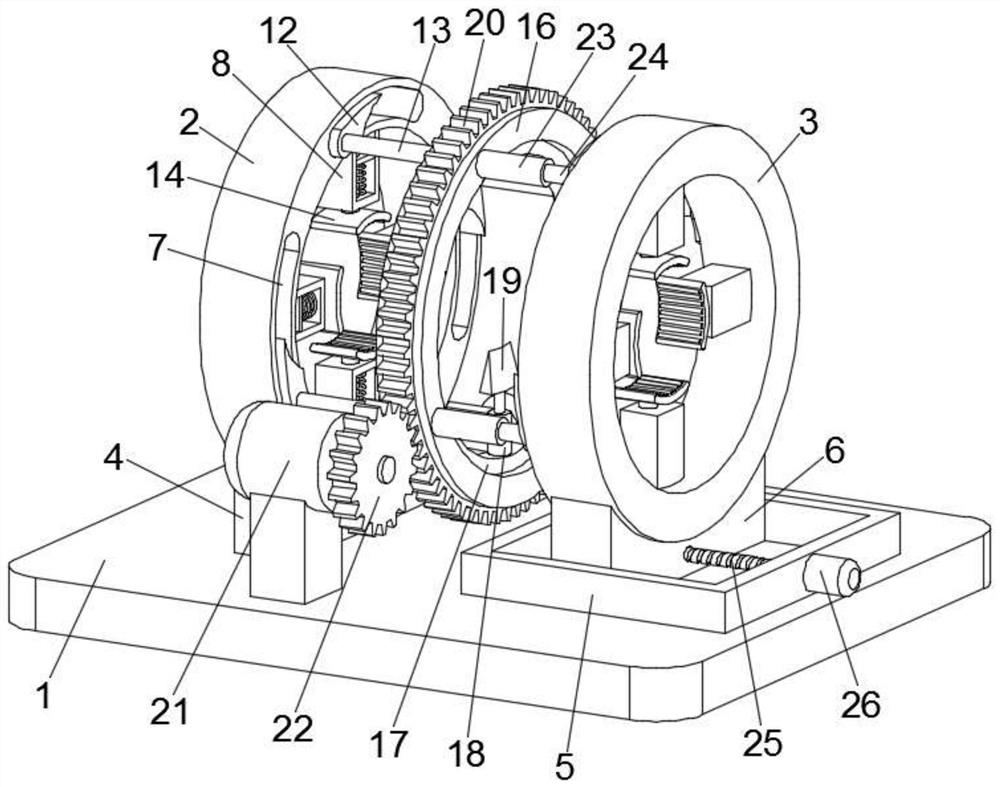
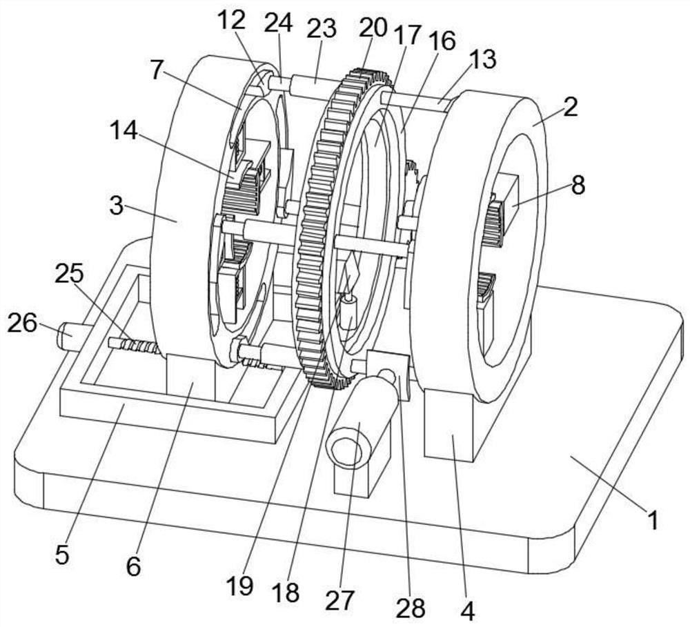
[0026]Seefigure 1 , A cable stripping device, comprising a base 1, a first support ring 2, a second support ring 3, and a mounting ring 16. The first support ring 2 is fixedly installed on the base 1 through a fixing base 4, and the base 1 is A sliding table 5 is also provided. A sliding seat 6 is fixed at the bottom of the second support ring 3. The sliding seat 6 is slidably embedded in the sliding table 5, and the mounting ring 16 is located between the first support ring 2 and the second support ring. Between ring 3;

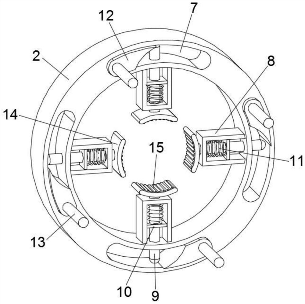
[0027]Seefigure 2 , The first support ring 2 and the second support ring 3 are evenly circumferentially distributed with several sets of clamping components, the clamping components include an arc-shaped groove 7, a fixed cylinder 8 and a pressure plate 14, the fixed cylinder 8 is provided with There is a mandrel 9 penetrating through the arc-shaped slot 7, a wedge block 12 matched with the mandrel 9 is movably clamped in the arc-shaped slot 7, and a pressure plate 1...

Embodiment 2

[0041]A cable stripping device includes a base 1, a first support ring 2, a second support ring 3, and a mounting ring 16. The first support ring 2 is fixedly installed on the base 1 through a fixing base 4, and the base 1 is also A sliding table 5 is provided, a sliding seat 6 is fixed at the bottom of the second support ring 3, the sliding seat 6 is slidably embedded in the sliding table 5, and the mounting ring 16 is located at the first support ring 2 and the second support ring Between 3;

[0042]The first support ring 2 and the second support ring 3 are both circumferentially evenly distributed with several groups of clamping components, the clamping components include an arc-shaped groove 7, a fixed cylinder 8 and a pressure plate 14, the fixed cylinder 8 is provided with A mandrel 9 passing through the arc-shaped slot 7, a wedge block 12 matching the mandrel 9 is movably clamped in the arc-shaped slot 7, and a pressure plate 14 is installed on the end of the mandrel 9 away from...


PUM


Abstract

The invention discloses a cable stripping device, which comprises a base, a first support ring, a second support ring and a mounting ring; a plurality of sets of clamping assemblies are evenly distributed on the first supporting ring and the second supporting ring in the circumferential direction. A rotating ring is further rotationally embedded in the mounting ring, a telescopic column is mountedon the inner wall of the rotating ring, a blade is fixedly mounted at the extending end of the telescopic column, and a rotating mechanism for driving the rotating ring is arranged on the base. A push plate is used for pushing a first connecting rod to rotate in the circumferential direction, so that the multiple sets of clamping assemblies on the first supporting ring and the second supporting ring are driven to clamp and fix the two ends of a cable, the rotating mechanism drives the blades on the rotating ring to rotate in the circumferential direction, and annular cutting of the cable skinis achieved. And finally, the second supporting ring is driven by a translation mechanism to be far away from the first supporting ring, so that the cut cable skin is stripped from the cable core, the automatic stripping of the cable is realized, cables with different diameters can be stripped, the processing efficiency is high, and the stripping quality is stable and reliable.

Description

Technical field[0001]The invention relates to the field of electric power technology, in particular to a cable stripping device.Background technique[0002]With the increasing level of industrialization, the power industry has developed more broadly. Cables are widely used in many fields such as electricity, manufacturing, and machinery. The amount of wires and cables is also greatly increasing, and the scope of coverage is also increasing. Wider. At present, when stripping cables, wire strippers are generally used to strip the cable skin at the end of the cable, but when it comes to cables with a larger diameter, it is difficult to use wire strippers to strip the cable, and the skin of the thick cable It adheres tightly to the cable core, and it is difficult to peel the cable from the cable core by manpower.Summary of the invention[0003]The object of the present invention is to provide a cable stripping device to solve the above-mentioned problems in the background art.[0004]In order...

Claims


Application Information

Patent Timeline
IPC IPC(8): H01R43/28H02G1/12
CPCH01R43/28H02G1/1265
Inventor 王广飞
Owner 王广飞
Why Eureka
Try Eureka