
Automatic grafting equipment for commercial plants

An automatic grafting and plant technology, applied in the direction of grafting, etc., can solve the problems of wood fixation and single function.

Pending Publication Date: 2021-03-02
周明鸿
View PDF6 Cites 1 Cited by
  • Summary
  • Abstract
  • Description
  • Claims
  • Application Information

AI Technical Summary

Benefits of technology

This new technology allows for better control over how trees are cut or shaped while still being joined together. It also includes an automatic moving system where each piece of tree remains connected during its formation process. Additionally, it uses a special type of tool called a lathe-like device instead of traditional tools like saws. Overall these technical improvements improve efficiency and accuracy in processing large numbers of timber materials.

Problems solved by technology

This patented technical problem addressed in this patents relates to improving the efficient and consistently successful process for joining branches from vegetation like trees by automating the procedure involved with traditional methods such as hand labor.

Method used


Image

  • Automatic grafting equipment for commercial plants
  • Automatic grafting equipment for commercial plants
  • Automatic grafting equipment for commercial plants

Examples


Embodiment 1

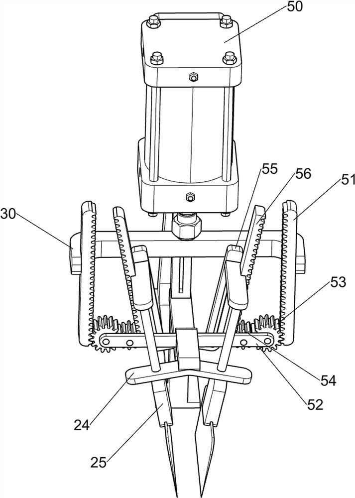
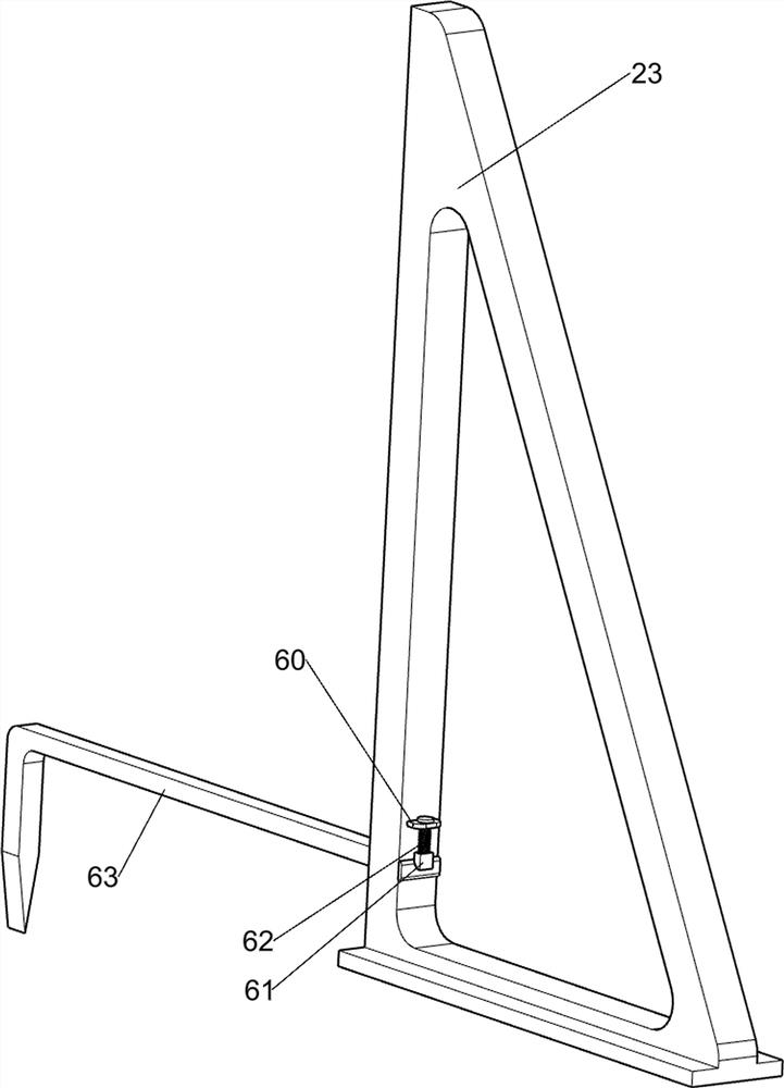
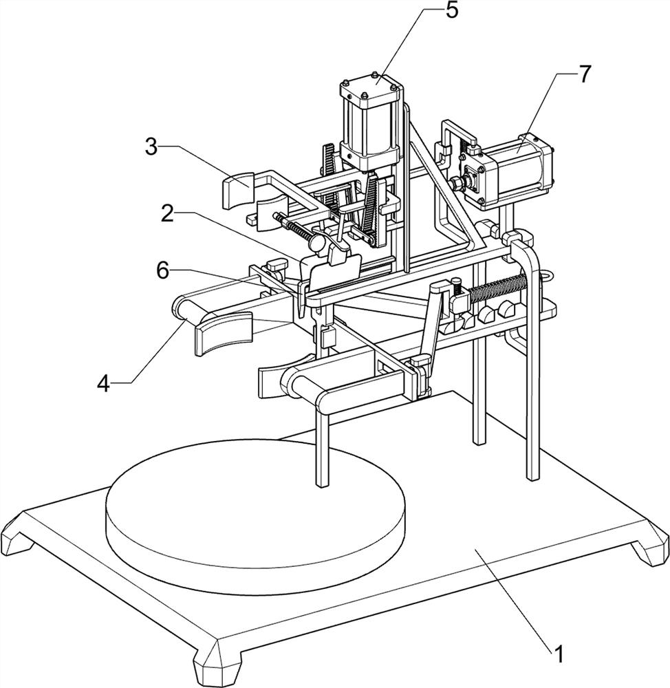
[0028] A commercial plant automatic grafting equipment, such as figure 1 , figure 2 , image 3 with Figure 5 As shown, it includes a base 1 , a cutting mechanism 2 and a grafting mechanism 3 , the base 1 is provided with a cutting mechanism 2 , and the cutting mechanism 2 is provided with a grafting mechanism 3 .

[0029] First people push the cutting mechanism 2 to the left, and the cutting mechanism 2 drives the grafting mechanism 3 to move to the left, then fix the branches to be grafted on the grafting mechanism 3, and then people can place the wood on the cutting mechanism 2, at this time The cutting part of the cutting mechanism 2 is located above the wood, and then people squeeze the cutting part of the cutting mechanism 2 downward, so that the cutting part of the cutting mechanism 2 can cut and slot the wood. After the slotting is completed, people can move the cutting part upwards and reset it , and push the cutting mechanism 2 to the right, the cutting mechanism...

Embodiment 2

[0034] On the basis of Example 1, such as figure 1 , Figure 4 , Figure 5 , Image 6 with Figure 7 As shown, the clamping mechanism 4 is also included, and the clamping mechanism 4 includes a fourth connecting block 40, a guide plate 41, a second sliding block 42, a fifth connecting block 43, a sixth connecting block 44, a limit block 45, a Three slide blocks 46, the first spring 47, the fixed plate 48 and the second spring 49; The symmetrical sliding type is provided with a second slider 42, the second slider 42 slides on the guide plate 41, the mounting table 22 is provided with a fixed plate 48, the fixed plate 48 is connected with the fourth connecting block 40, and the sliding type on the fixed plate 48 Be provided with the 5th connecting block 43, the 5th connecting block 43 left side rotation type is provided with two the 6th connecting block 44, the 6th connecting block 44 is connected with the second sliding block 42 rotating type, fixed plate 48 right sides are e...


PUM


Abstract

The invention relates to grafting equipment, in particular to automatic grafting equipment for commercial plants. The automatic grafting equipment for the commercial plants can be used for fixing woodwith different sizes and has various functions. The automatic grafting equipment for the commercial plants comprises a base and a grafting mechanism, wherein a cutting mechanism is arranged on the base; and the grafting mechanism is arranged on the cutting mechanism. Cutting and grooving of wood are achieved through the cutting mechanism, then downward movement of branches is achieved under cooperation of the grafting mechanism, in this way, the grafting action can be achieved, and the grafting mechanism can clamp the branches; and through the arrangement of a clamping mechanism, wood with the same size is fixed, and thus different kinds of wood can be grafted.

Description


Claims


Application Information

Patent Timeline
Owner 周明鸿
Learn More