
On-board Attitude Compensation Method and System for Deep Space Probe Thrust Vector Deviation

A deep space detector and thrust vector technology, applied in the field of attitude dynamics, can solve the problems that cannot be applied in the field of deep space detection, and achieve the effects of reducing fuel consumption, prolonging life, and improving the accuracy of orbit change

Active Publication Date: 2022-07-12
SHANGHAI SATELLITE ENG INST
View PDF7 Cites 0 Cited by
  • Summary
  • Abstract
  • Description
  • Claims
  • Application Information

AI Technical Summary

Problems solved by technology

This method can only be adapted to the orbit control of spacecraft with high-precision orbit determination conditions, and cannot be applied in the field of deep space exploration

Method used


Image

  • On-board Attitude Compensation Method and System for Deep Space Probe Thrust Vector Deviation
  • On-board Attitude Compensation Method and System for Deep Space Probe Thrust Vector Deviation
  • On-board Attitude Compensation Method and System for Deep Space Probe Thrust Vector Deviation

Examples


Embodiment 1

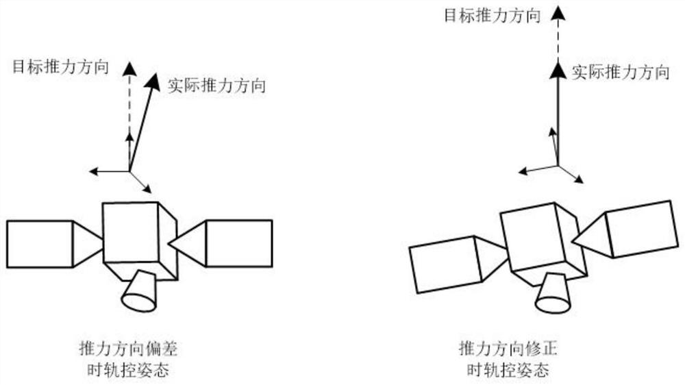
[0053] The invention proposes an on-board attitude compensation method for the thrust vector deviation of a deep space probe, which aims to reduce the deviation of the thrust direction during orbit control of the deep space probe, improve the orbit control accuracy and save fuel consumption.

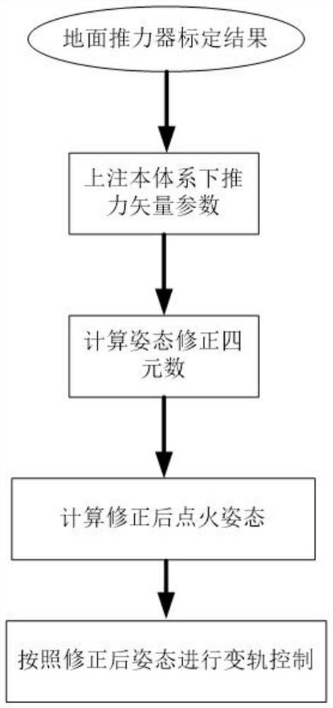
[0054] According to an on-board attitude compensation method for a thrust vector deviation of a deep space probe provided by the present invention, such as Figure 1-2 shown, including:

[0055] Step M1: Calculate the attitude compensation correction amount during orbit control according to the result of the engine thrust direction calibration on the ground;

[0056] Step M2: The attitude compensation correction amount during the orbit control is injected into the vehicle to compensate for the thrust direction deviation of the spacecraft thruster, so as to improve the orbit change accuracy.

[0057] Preferably, the step M1 includes:

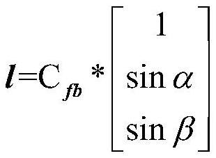
[0058] Step M1.1: Calculate the projection l of the...


PUM


Abstract

The present invention provides an on-board attitude compensation method and system for a thrust vector deviation of a deep space probe. During the period, the attitude compensation correction amount is injected into the device and implemented. The invention is used for compensating the thrust direction deviation of the spacecraft thruster, so as to improve the accuracy of orbit change.

Description

technical field [0001] The invention relates to the field of attitude dynamics, in particular, to a method and system for on-board attitude compensation of thrust vector deviation of a deep space probe. Background technique [0002] In order to achieve the goal of deviating from the earth's gravity, entering a cruise orbit or entering a transfer orbit between stars and earth, and re-entering planets and orbiting flying stars, deep space probes need to change orbits multiple times to meet the requirements of fuel saving and orbit accuracy correction. At the same time, in key orbit changes such as re-entry and planet capture, there is usually only one chance of orbit change, and high orbit control accuracy is required to ensure subsequent missions. During the planetary capture stage, the probe needs to be ignited to decelerate, and the deviation of the ignition direction is very likely to cause the probe to fail to form an orbit, and if it is more serious, the mission to crash...

Claims


Application Information

Patent Timeline
Patent Type & Authority Patents(China)
IPC IPC(8): G05D1/08B64G1/24B64G1/40
CPCB64G1/244B64G1/40
Inventor 吕旺王伟褚英志朱新波方宝东信思博
Owner SHANGHAI SATELLITE ENG INST
Learn More