Control rope tensioning device

A technology of tensioning device and control rope, which is used in auxiliary equipment for rope making, transportation and packaging, textiles and papermaking, etc., can solve the problems of control rope rebound, low production efficiency, etc., achieve uniform increase in force and improve efficiency , the effect of improving the effect

Inactive Publication Date: 2021-03-02
台州市和德绳业有限公司
View PDF0 Cites 2 Cited by
  • Summary
  • Abstract
  • Description
  • Claims
  • Application Information

AI Technical Summary

Problems solved by technology

[0002] During the production process of the control rope, the pulling method is generally used to fully stretch the control rope, even if the control rope does not have the ability to deform, in order to improve the safety and stability of the control rope during use, but in the pulling operation When the rope is used, the manipulation rope is prone to rebound, and it needs to be pulled many times, and the production efficiency is low.

Method used


Image

  • Control rope tensioning device
  • Control rope tensioning device
  • Control rope tensioning device

Examples


specific Embodiment approach

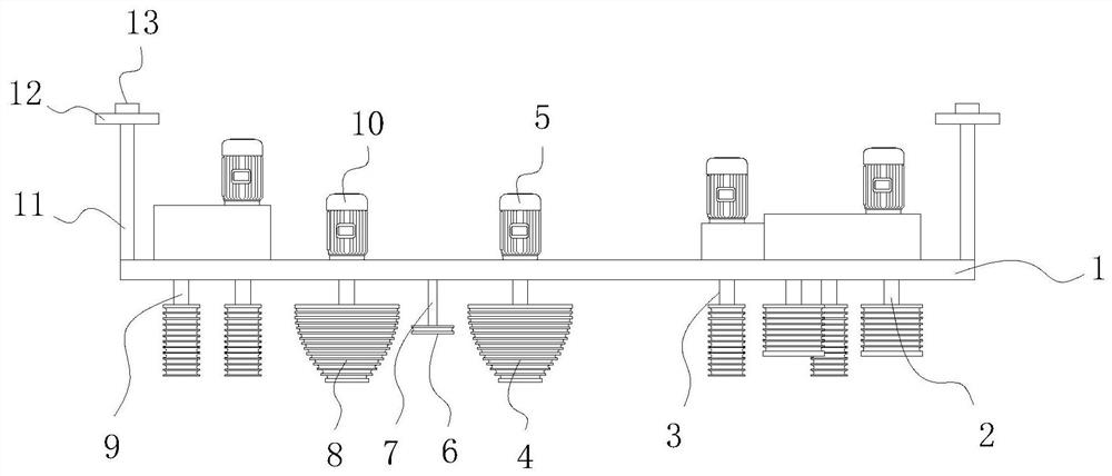
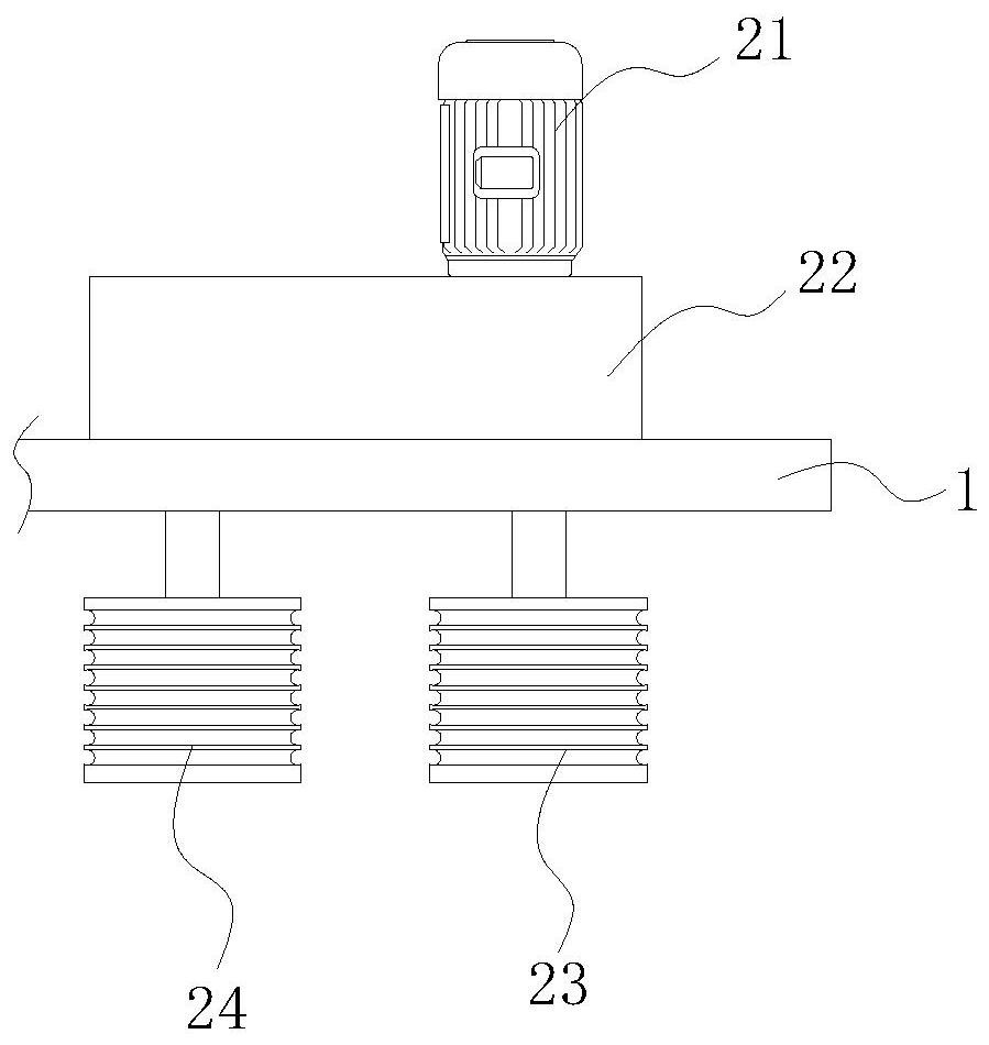
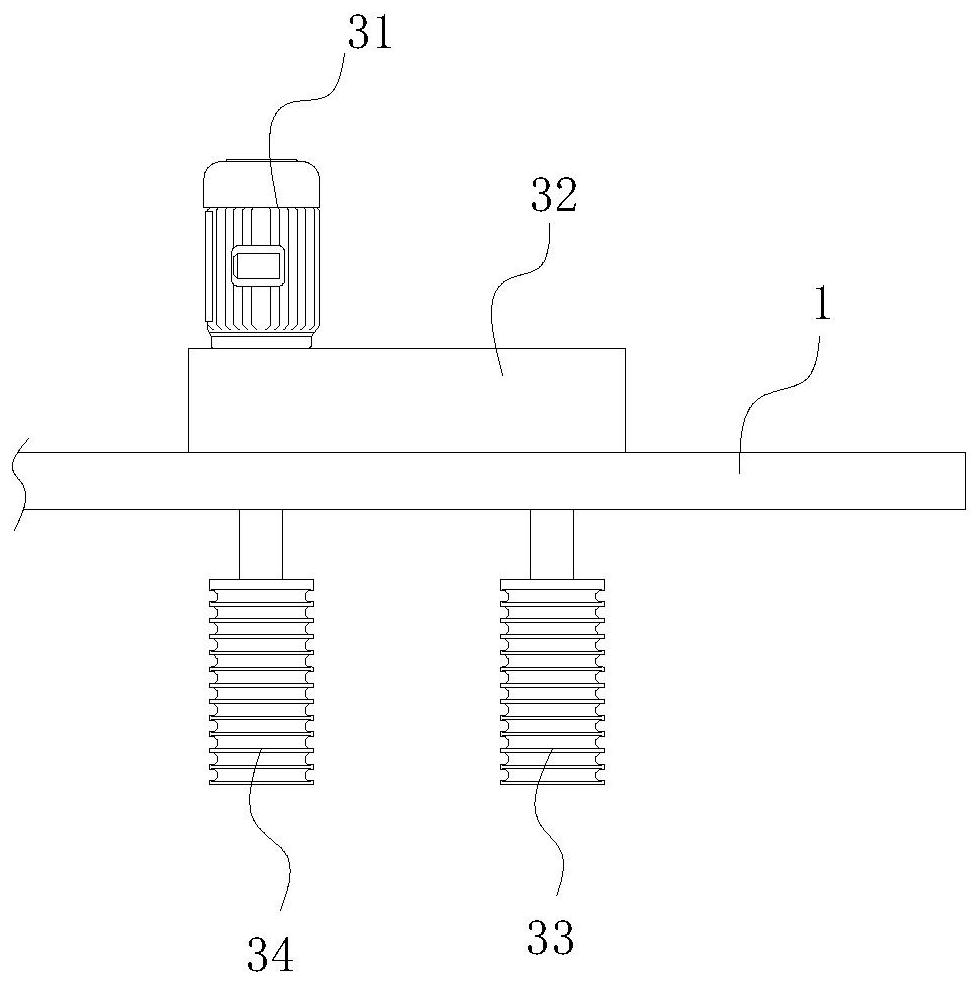
[0029]The specific embodiment: the control rope is crossed around between the first rope-in ​​wheel 23 and the second rope-in ​​wheel 24, and the first motor 21 is run, and the first motor 21 drives the first rope-in ​​wheel through the first gear box 22 23 and the second rope entering wheel 24 rotate in opposite directions to realize the guidance of the steering rope and the pretensioning of the steering rope, and the steering rope is wound in a cross shape between the first rope locking wheel 33 and the second rope locking wheel 34, Run the second motor 31, the second motor 31 drives the first rope locking wheel 33 and the second rope locking wheel 34 to rotate in opposite directions through the second gear box 32, so as to prevent the control rope from rebounding in the direction of the rope inlet assembly 2, that is, Realize the locking of the rope inlet end of the control rope, wind the control rope in a cross shape between the third lock wheel 93 and the fourth lock wheel...


PUM


Abstract

The invention provides a control rope tensioning device. The control rope tensioning device comprises a carrier plate, a rope feeding assembly used for guiding a control rope to move is installed on one side face of the carrier plate, a first rope locking assembly used for preventing the control rope from rebounding is arranged obliquely below the rope feeding assembly, a second rope locking assembly used for preventing the control rope from rebounding is installed on the side, away from the first rope locking assembly, of one side face of the carrier plate, a first conical wheel and a secondconical wheel which rotate oppositely and are used for tensioning the control rope are arranged between the first rope locking assembly and the second rope locking assembly, the side, facing the carrier plate, of the first conical wheel is connected with the output end of a first gear motor through a rotating shaft, and the side, facing the carrier plate, of the second conical wheel is connected with the output end of a second gear motor through a rotating shaft. Compared with the prior art, the control rope tensioning device has the following beneficial effects that the tensioned control ropeis prevented from rebounding, the tensioning efficiency of the control rope is improved, step-by-step tensioning is achieved, and the stress of the control rope is evenly increased.

Description

technical field [0001] The invention relates to a control rope tensioning device, which belongs to the technical field of control rope production. Background technique [0002] During the production process of the control rope, the control rope is generally stretched completely by pulling. When the rope is used, the manipulation rope is prone to rebound, and it needs to be pulled many times, and the production efficiency is low. Contents of the invention [0003] Aiming at the deficiencies in the prior art, the purpose of the present invention is to provide a tensioning device for a control rope to solve the problems raised in the above-mentioned background art. [0004] In order to achieve the above object, the present invention is achieved through the following technical solutions: a steering rope tensioning device, including a carrier plate, a side of the carrier plate is installed with a rope-incoming assembly for guiding the movement of the steering rope, and the rop...

Claims


Application Information

Patent Timeline
Patent Type & Authority Applications(China)
IPC IPC(8): D07B7/02B65H51/06B65H51/32B65H57/14B65H59/10
CPCB65H51/06B65H51/32B65H57/14B65H59/10B65H2701/35D07B7/02
Inventor 蔡恩军
Owner 台州市和德绳业有限公司
Why Eureka
Try Eureka