
Smart home camera device

A camera device and smart home technology, which is applied in signal devices, image communication, television, etc., can solve the problems of small monitoring field of view of the device, inability to monitor the outdoor environment, and unfavorable outdoor environment monitoring, so as to improve the shooting and monitoring field of view and improve the monitoring Effect, the effect of reducing blind spots in shooting

Inactive Publication Date: 2021-03-02
广州初色科技有限公司
View PDF1 Cites 2 Cited by
  • Summary
  • Abstract
  • Description
  • Claims
  • Application Information

AI Technical Summary

Problems solved by technology

[0002] The smart home camera device installed outdoors can monitor the outdoor environment, and it is convenient to observe and record the conditions of the outdoor environment. The existing smart home camera device is fixedly installed outdoors and cannot be moved, resulting in a wide range of field of view for device monitoring. Small, unable to monitor the outdoor environment well
[0003] For example, the Chinese patent application number is 201910340875.9, a smart home camera device for home life, which is basically described as: including a controller support frame installed on the top and an electric telescopic rod and a rotating shaft that are rotatably connected inside the support frame. The bottom end of the rod is fixedly set with a driven gear, and the bottom of the electric telescopic rod is fixedly connected with a fixing frame located below the support frame. The smart home camera device for home life is coordinated by the first positive and negative motor and the second positive and negative motor. Carry out and monitor the position adjustment, but the flexibility of this adjustment method is poor in use. It can only realize the horizontal rotation adjustment angle, and the range of modulation angle is small, which is not conducive to better monitoring of the outdoor environment and is not conducive to the convenience of use. improvement

Method used


Image

  • Smart home camera device
  • Smart home camera device
  • Smart home camera device

Examples


Embodiment Construction

[0057] The following will clearly and completely describe the technical solutions in the embodiments of the present invention with reference to the accompanying drawings in the embodiments of the present invention. Obviously, the described embodiments are only some, not all, embodiments of the present invention. Based on the embodiments of the present invention, all other embodiments obtained by persons of ordinary skill in the art without making creative efforts belong to the protection scope of the present invention.

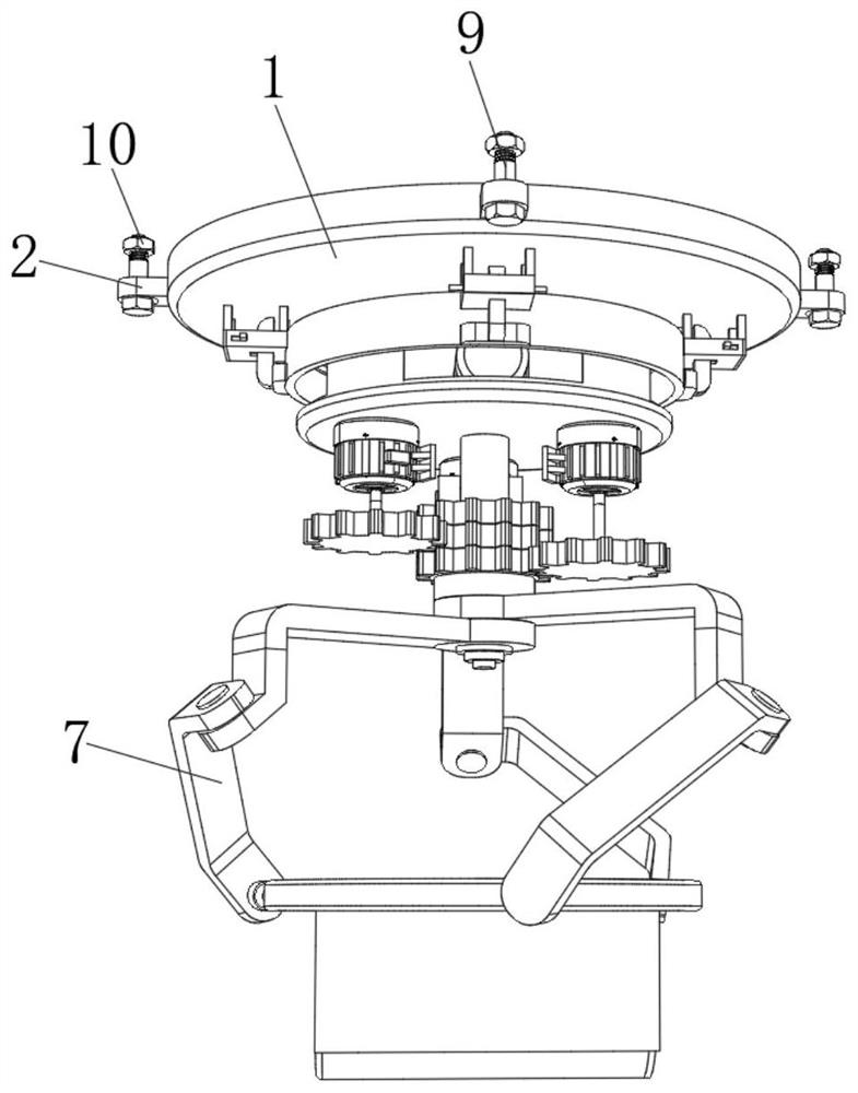
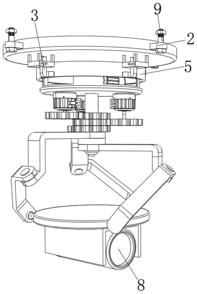
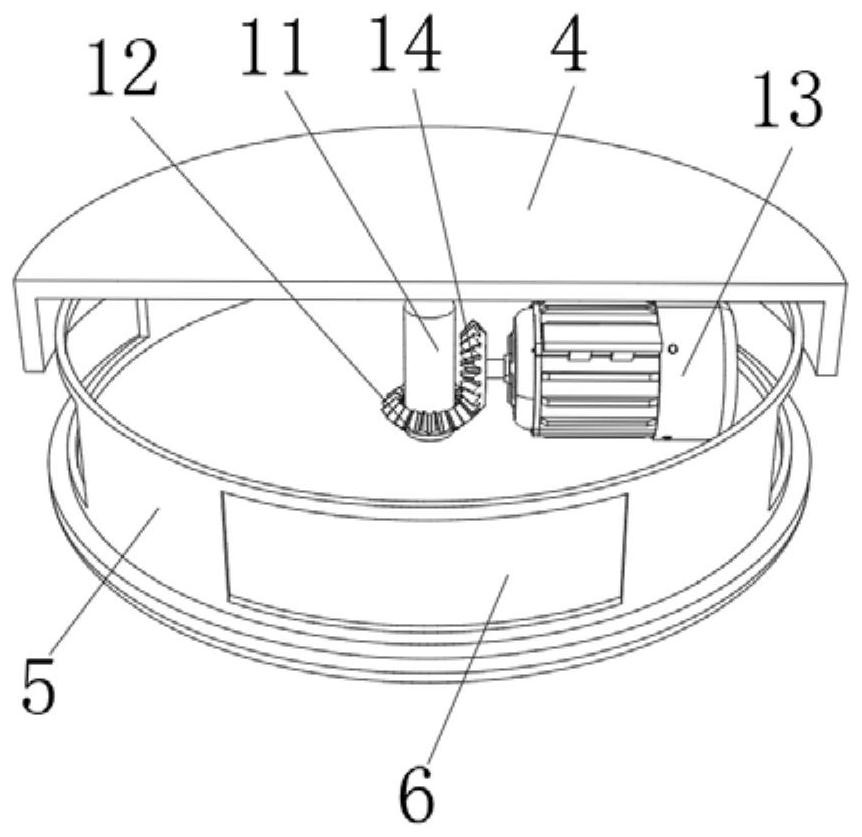
[0058] see Figure 1-5 , the present invention provides a technical solution: a camera device for smart home use, including a fixed top plate 1, a fixed block 2 is fixedly connected to the outer surface of the fixed top plate 1, and a quick installation device 3 is fixedly connected to the lower surface of the fixed top plate 1. The inboard of installation device 3 is provided with annular fixed disk 4, and the top inwall of annular fixed disk 4 is provided wi...


PUM


Abstract

The invention relates to the technical field of smart home camera devices, and discloses a smart home camera device. The device comprises a fixed top plate, a fixed block is fixedly connected to the outer side surface of the fixed top plate, a quick mounting device is fixedly connected to the lower surface of the fixed top plate, and an annular fixed disc is arranged at the inner side of the quickmounting device. An annular rotating frame is arranged on the inner wall of the top of the annular fixed disc, and the lower surface of the annular rotating frame is fixedly connected with a fixing disc. According to the smart home camera device, a driving gear and a driven gear are driven by a driving motor to cooperate with a first rotating frame and a second rotating frame to drive the connecting fixing disc to rotate so as to perform multi-angle adjustment on a monitoring camera, so that the camera device has better flexibility in use, and can perform accurate monitoring camera shooting on any position; and shooting blind areas and shooting dead angles are reduced, the outdoor environment can be better monitored, and the use convenience is improved.

Description

technical field [0001] The invention relates to the technical field of smart home camera devices, in particular to a smart home camera device. Background technique [0002] The smart home camera device installed outdoors can monitor the outdoor environment, and it is convenient to observe and record the conditions of the outdoor environment. The existing smart home camera device is fixedly installed outdoors and cannot be moved, resulting in a wide range of field of view for device monitoring. It is small and cannot monitor the outdoor environment well. [0003] For example, the Chinese patent application number is 201910340875.9, a smart home camera device for home life, which is basically described as: including a controller support frame installed on the top and an electric telescopic rod and a rotating shaft that are rotatably connected inside the support frame. The bottom end of the rod is fixedly set with a driven gear, and the bottom of the electric telescopic rod is...

Claims


Application Information

Patent Timeline
Patent Type & Authority Applications(China)
IPC IPC(8): F16M13/02F16M11/12F16M11/18H04N7/18H04N5/225G08B1/00G03B17/55
CPCF16M13/02F16M11/121F16M11/041F16M11/18H04N7/18G08B1/00G03B17/55H04N23/50
Inventor 鲍小芬
Owner 广州初色科技有限公司
Learn More