Machining track deformation compensation method and system

A technology of deformation compensation and processing trajectory, which is applied in the field of processing trajectory deformation compensation method and system, can solve the problems of not taking into account the deformation of feature points and feature points, the inability to complete one stroke, and the reduction of trajectory correction and deformation compensation. Problems, to achieve Easy to modify and edit the effect

Pending Publication Date: 2021-03-02
深圳群宾精密工业有限公司
View PDF0 Cites 1 Cited by
  • Summary
  • Abstract
  • Description
  • Claims
  • Application Information

AI Technical Summary

Problems solved by technology

[0002] In the modern manufacturing industry, some scenarios require technicians to formulate corresponding tool head operation trajectories according to different batches of workpieces at the job site. In many cases, specific mesh trajectories are required. The following exist during mesh trajectory operations Disadvantages: its trajectory is distributed on the surface of the workpiece in a net shape, and it cannot be completed in one stroke; the operation trajectory needs to surround a large number of hole positions; the state of the tool head needs to be switched during the operation process, such as the switch amount of the glue when dispensing; Subjective settings are required to avoid certain parts; there are special connection requirements between multiple strokes of the trajectory, such as T-shaped intersections requiring proper avoidance; in view of the above technical problems, the industry usually uses direct teaching or offline teaching simulation using software In combination, there is also a more general scheme of using 2D or 3D vision system for auxiliary positioning
Among them, the combination of teaching and offline is currently the most common method. The disadvantage of this solution is that it requires engineers to spend a lot of time on manual teaching operations.
[0003] At present, there are a few 2D and 3D visual trajectory correction solutions on the market. What they have in common is that they use the visually captured point information to bind the trajectory points, and all of them require practical high-precision images for splicing and precision calibration. This method Only use the position change of the feature point to correct the position of the track point, without considering the more subtle deformation problems between the feature point and the feature point, such as the workpiece on a straight line between two round hole feature points Bending greatly reduces the deformation compensation capability of trajectory correction. Such a trajectory correction scheme is not suitable for some plate-like workpieces with many holes and narrow sides.

Method used


Image

  • Machining track deformation compensation method and system

Examples


Embodiment Construction

[0023] In order to describe the technical solution of the present invention more clearly and completely, the present invention will be further described below in conjunction with the accompanying drawings.

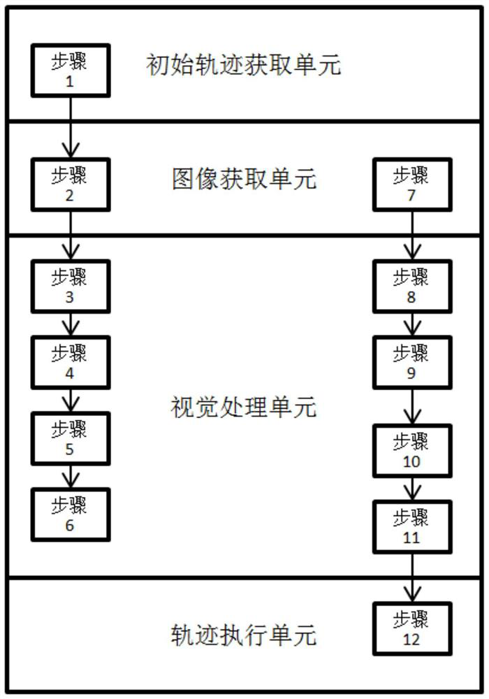
[0024] Please refer to figure 1 , the present invention proposes a processing trajectory deformation compensation method, the processing trajectory deformation compensation method includes the following steps: Step 1: perform trajectory editing operations or import trajectory from outside to obtain the initial trajectory; Step 2: acquire images; Step 3: The image obtained in step 2 is pre-processed such as splicing and calibration; step 4: set multiple anchor point measurement boxes in the image after step 3 processing and calculate the anchor point within the corresponding range; step 5: in the initial trajectory point Generate the track point measurement box at the position, and set the track point coordinate calculation method corresponding to each track point measureme...


PUM


Abstract

The invention provides a machining track deformation compensation method and system, and the method comprises the following steps: obtaining an initial track; acquiring an image; performing preprocessing operations such as splicing and calibration on the acquired images; setting a plurality of anchoring point measuring boxes, and calculating in a corresponding range to obtain anchoring points; generating track point measurement boxes at the initial track point positions, and setting track point coordinate calculation modes corresponding to the track point measurement boxes; obtaining an anchoring point; updating the position of the corresponding anchored track point measurement box according to the obtained coordinates of the anchoring point; calculating coordinates in the range of the track point measuring box in a set mode and updated to the corresponding track points, and obtaining a correction track; directly executing track correction; completing the steps through an initial trackacquisition unit, an image acquisition unit, a visual processing unit and a track execution unit of the machining track deformation compensation system, and deviation rectification or positioning ofa large complex track can be achieved in a simple mode.

Description

technical field [0001] The invention relates to the technical field of automatic processing, in particular to a processing track deformation compensation method and system. Background technique [0002] In the modern manufacturing industry, some scenarios require technicians to formulate corresponding tool head operation trajectories according to different batches of workpieces at the job site. In many cases, specific mesh trajectories are required. The following exist during mesh trajectory operations Disadvantages: its trajectory is distributed on the surface of the workpiece in a net shape, and it cannot be completed in one stroke; the operation trajectory needs to surround a large number of hole positions; the state of the tool head needs to be switched during the operation process, such as the switch amount of the glue when dispensing; Subjective settings are required to avoid certain parts; there are special connection requirements between multiple strokes of the traje...

Claims


Application Information

Patent Timeline
Patent Type & Authority Applications(China)
IPC IPC(8): G06T19/20G06T15/00G06T7/70
CPCG06T15/00G06T19/20G06T2207/10012G06T7/70
Inventor 席豪圣陈方
Owner 深圳群宾精密工业有限公司
Why Eureka
Try Eureka