Three-section V-shaped series-parallel combined magnetic pole adjustable flux motor

A technology of combined magnetic poles and flux motors, which is applied in the direction of magnetic circuits, synchronous machines, electric components, etc., can solve the problems that the advantages of series-parallel adjustable flux motors cannot be taken into account, so as to achieve the effect of magnetic adjustment, improve stability, Reduced effect of magnetizing current pulses

Active Publication Date: 2021-03-02
HARBIN INST OF TECH
View PDF12 Cites 1 Cited by
  • Summary
  • Abstract
  • Description
  • Claims
  • Application Information

AI Technical Summary

Problems solved by technology

[0003] The purpose of the present invention is to solve the problem that the existing technology cannot take into account the advantages of the series-parallel adjustable flux motor, and provides a three-stage V-type series-parallel combined magnetic pole adjustable flux motor

Method used


Image

  • Three-section V-shaped series-parallel combined magnetic pole adjustable flux motor
  • Three-section V-shaped series-parallel combined magnetic pole adjustable flux motor
  • Three-section V-shaped series-parallel combined magnetic pole adjustable flux motor

Examples


specific Embodiment approach 1

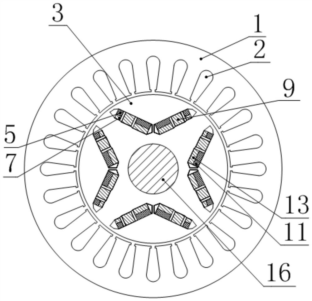
[0033] Specific implementation mode one: the following combination Figure 1 to Figure 7 To illustrate this embodiment, the three-stage V-type series-parallel combination magnetic pole adjustable flux motor described in this embodiment includes a stator core 1, a stator winding 2, a rotor core 3 and a rotating shaft 16; the rotor core 3 is fixed on the rotating shaft 16, And located inside the stator core 1, the armature winding 2 is arranged on the stator core 1;

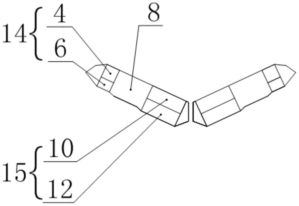
[0034] A V-shaped permanent magnet slot is arranged under each magnetic pole of the rotor core 3. The V-shaped permanent magnet slot is composed of two in-line slots arranged symmetrically. The in-line slot is a three-stage structure, and along the length direction From the outside to the inside, the outer tank body 14, the middle tank body 8 and the inner tank body 15 are sequentially connected to form, and the outer tank body 14 is composed of a No. 1 high-coercivity permanent magnet slot 4 and a No. 1 low-coerci...

specific Embodiment approach 2

[0055] Embodiment 2: The difference between this embodiment and Embodiment 1 is that the layout of two pairs of permanent magnets connected in series with the magnetic circuit is divided into the following two types:

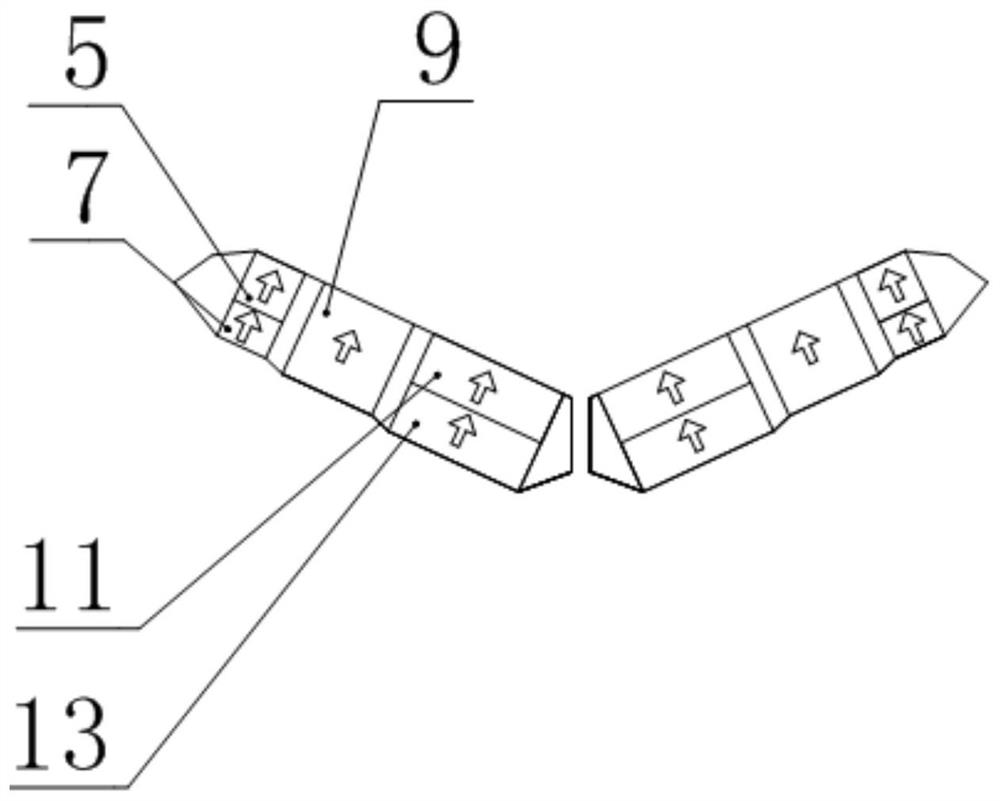
[0056] The first layout method: No. 1 high-coercivity permanent magnet slot 4 and No. 2 high-coercivity permanent magnet slot 10 are close to the inside of the V-shaped permanent magnet slot at the same time, No. 1 low-coercivity permanent magnet slot 6 and No. 2 low-coercivity permanent magnet slot The coercivity permanent magnet groove 12 is close to the outside of the V-shaped permanent magnet groove at the same time;

[0057] The second layout mode: No. 1 high-coercivity permanent magnet slot 4 and No. 2 high-coercivity permanent magnet slot 10 are close to the outside of the V-shaped permanent magnet slot at the same time, No. 1 low-coercivity permanent magnet slot 6 and No. 2 low-coercivity permanent magnet slot The coercivity permanent magnet groove 12 is...


PUM

PropertyMeasurementUnit
Coercivityaaaaaaaaaa

Abstract

The invention discloses a three-section V-shaped series-parallel combined magnetic pole adjustable flux motor, belongs to the field of permanent magnet motors, and aims to solve the problem that the advantages of a series-parallel adjustable flux motor cannot be considered in the prior art. A V-shaped permanent magnet groove is formed below each magnetic pole of a rotor core, each V-shaped permanent magnet groove is formed by symmetrically arranging two linear groove bodies, each linear groove body is of a three-section structure, and each linear groove body is formed by sequentially communicating an outer groove body, a middle groove body and an inner groove body from outside to inside in the length direction. The outer groove body is formed by communicating a first high-coercivity permanent magnet groove and a first low-coercivity permanent magnet groove in parallel in the thickness direction, and the inner groove body is formed by communicating a second high-coercivity permanent magnet groove and a second low-coercivity permanent magnet groove in parallel in the thickness direction. The high-coercivity permanent magnets are arranged in the high-coercivity permanent magnet grooves, and low-coercivity permanent magnets are arranged in the low-coercivity permanent magnet grooves.

Description

technical field [0001] The invention relates to a wide speed regulation technology of a permanent magnet motor, which belongs to the field of permanent magnet motors. Background technique [0002] Permanent magnet synchronous motor has become a common drive motor for new energy vehicles due to its advantages of high power density and high efficiency. However, this type of motor has disadvantages such as difficulty in adjusting the permanent magnet magnetic field and low efficiency when the field is weakened. In response to the above problems, scholars have proposed an adjustable flux motor with an adjustable permanent magnet field. This motor can change the magnetization state of the permanent magnet by applying d-axis charging and demagnetizing current pulses, so as to expand the motor speed regulation range. the goal of. Compared with an adjustable flux motor using only one low-coercivity permanent magnet, a motor with a combined pole structure of high-coercivity and low-...

Claims


Application Information

Patent Timeline
IPC IPC(8): H02K1/27H02K1/24H02K21/02
CPCH02K1/2766H02K1/24H02K21/028H02K2213/03
Inventor 王明峤郑萍佟诚德乔光远梁晓宇刘法亮
Owner HARBIN INST OF TECH
Why Eureka
Try Eureka