Centralized transmission type xenon excimer light source ozone generator
An ozone generator and excimer technology, applied in the direction of ozone preparation, cooling/ventilation/heating transformation, disinfection, etc., can solve the problem of ozone reduction and other problems
- Summary
- Abstract
- Description
- Claims
- Application Information
AI Technical Summary
Problems solved by technology
Method used
Image

Examples
Embodiment 1
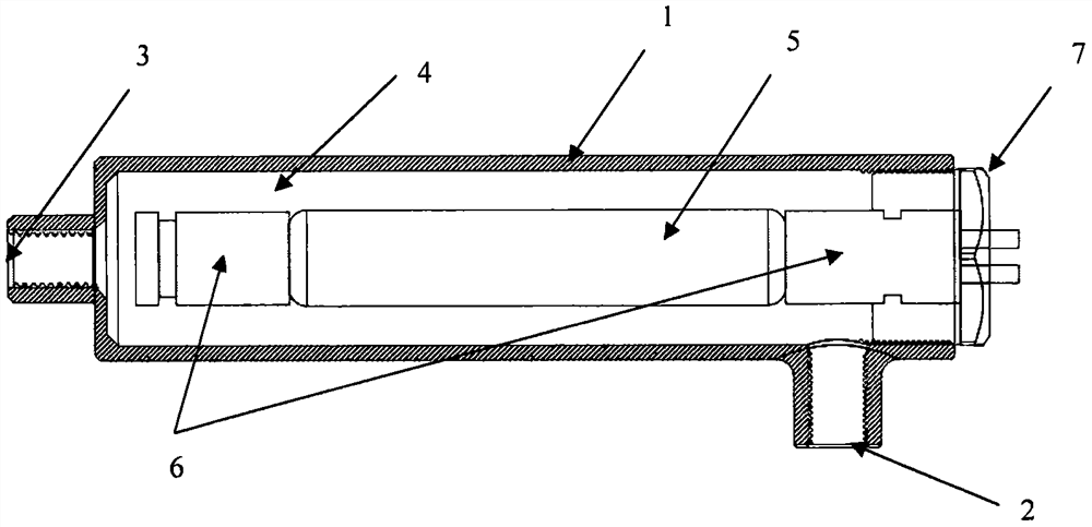
[0050] Embodiment 1: a kind of design of " enclosed xenon excimer ozone excitation chamber ", such as figure 2 shown. exist figure 2 Among them, 1 is the bulkhead of the closed xenon excimer ozone excitation chamber, 2 and 3 are two air holes of the closed xenon excimer ozone excitation chamber, one of which can be used as an air inlet, and the other can be used as an outlet (row) air hole ; 4 is the cavity inside the closed xenon excimer ozone excitation chamber, 5 is the quartz tube part of the xenon excimer lamp, 6 is the ceramic base of the xenon excimer lamp, and 7 is the closed xenon excimer ozone excitation The head of the cabin. exist figure 2 After the two ports of the enclosed xenon excimer ozone excitation chamber shown are closed, the enclosed xenon excimer ozone excitation chamber should be able to withstand the gas pressure generated by the gas pressure device, but the air pressure generated by the pressure gas device should be less than that of the xenon ...
Embodiment 3
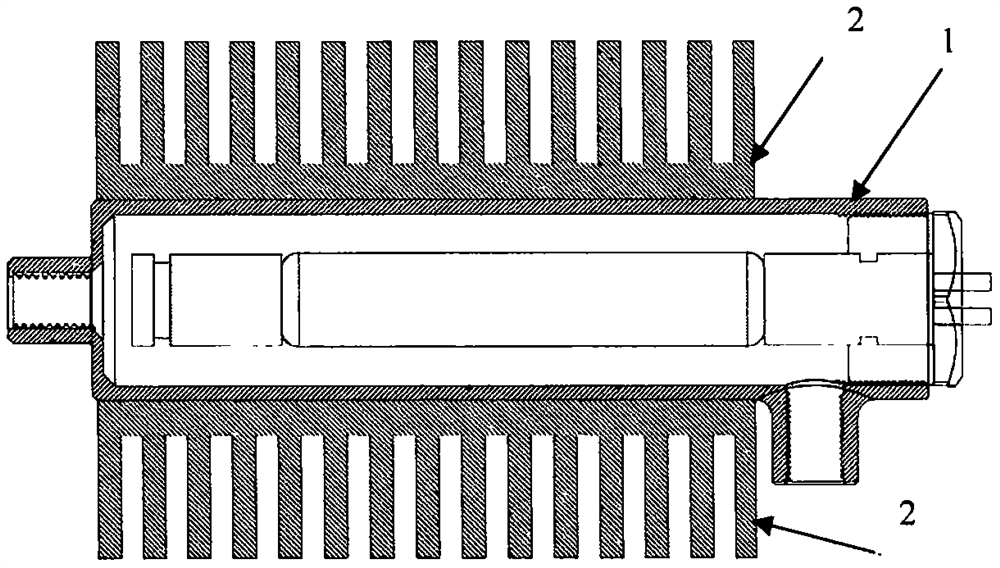
[0051] Embodiment 3: a kind of design of " enclosed xenon excimer ozone excitation cabin " that metal radiator is installed, as image 3 shown. exist image 3 Among them, the designer still adopts the design of embodiment 2 for the closed xenon excimer ozone excitation chamber, the difference is that a metal heat sink is designed and installed on the outer wall of the closed xenon excimer ozone excitation chamber. exist image 3 Among them, 1 is a closed xenon excimer ozone excitation chamber, and 2 is a metal heat sink. This heat dissipation method uses the airflow generated by the temperature difference on the metal heat sink to automatically spread the heat from the closed xenon excimer ozone excitation chamber to the surrounding air, thereby reducing the heat generated by the lighting of the xenon lamp.
Embodiment 4
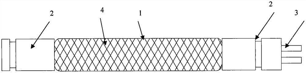
[0052] Embodiment 4: a kind of design of " enclosed xenon excimer ozone excitation chamber " that metal heat sink and cooling fan are installed, as Figure 4 shown. exist Figure 4 Among them, the designer still adopts the design of embodiment 2 for the closed xenon excimer ozone excitation chamber, the difference is that on the outer wall of the closed xenon excimer ozone excitation chamber, a metal radiator with cooling fan is designed and installed. exist Figure 4 Among them, 1 is a closed xenon excimer ozone excitation chamber, 2 is a metal heat sink, 3 is a cooling fan, and 4 is the blowing direction of the cooling fan. exist Figure 4 In the design of the design, the designer added a fan blowing to the heat sink, blowing the cold air around the outside to the heat sink, and blowing away the heat conducted from the closed xenon excimer ozone excitation chamber to the heat sink. this way with image 3 Compared with the design project, it belongs to the active heat d...
PUM
 Abstract
Description
Claims
Application Information
 - R&D Engineer
- R&D Manager
- IP Professional
- Industry Leading Data Capabilities
- Powerful AI technology
- Patent DNA Extraction
Browse by: Latest US Patents, China's latest patents, Technical Efficacy Thesaurus, Application Domain, Technology Topic.
© 2024 PatSnap. All rights reserved.Legal|Privacy policy|Modern Slavery Act Transparency Statement|Sitemap