Supercharge Your Innovation With Domain-Expert AI Agents!

GAS flow METER

A technology of gas flowmeter and flowmeter, which is applied in the direction of volume measurement, liquid/fluid solid measurement, flow/mass flow measurement, etc. It can solve filter mesh clogging, filter mesh clogging, filter pressure loss increase, etc. question

Pending Publication Date: 2021-03-05
ORMON CORP
View PDF0 Cites 0 Cited by
  • Summary
  • Abstract
  • Description
  • Claims
  • Application Information

AI Technical Summary

Problems solved by technology

[0003] Therefore, dust may accumulate in the filter and clogging may occur in the filter.
In addition, if moisture enters the gas flow meter, especially if the gas flow meter is installed in a cold area, sometimes such moisture freezes and causes the mesh of the filter to clog
If such clogging occurs, the pressure loss in the filter increases, which hinders the flow of gas in the gas flowmeter.

Method used


Image

  • GAS flow METER
  • GAS flow METER
  • GAS flow METER

Examples


Embodiment Construction

[0033] Hereinafter, embodiments of the present invention will be described with reference to the drawings.

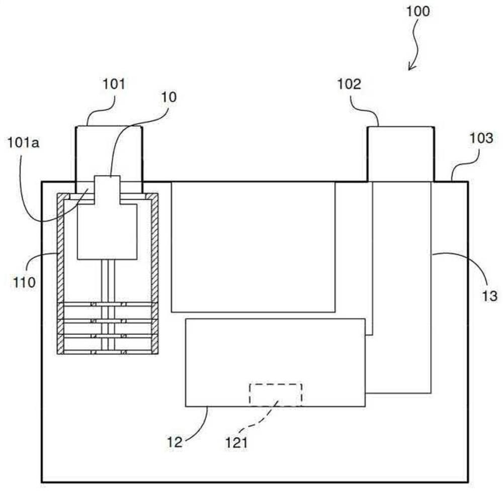
[0034] Such as figure 1 As shown, the gas flow meter 100 of the embodiment has a shut-off valve 10 and a filter device 11 (in figure 1 Only the support portion 110 is shown in . The stop valve 10 opens and closes the inflow opening 101 a communicating with the flowmeter inlet 101 of the gas flowmeter 100 and facing the inner opening of the gas flowmeter body 103 . The filter device 11 covers the opening 101 a and removes dust from the gas flowing in from the flowmeter inlet 101 . Since dust is removed by the filter device 11, high-precision flow measurement can be performed in the flow measurement unit 12 provided on the downstream side.

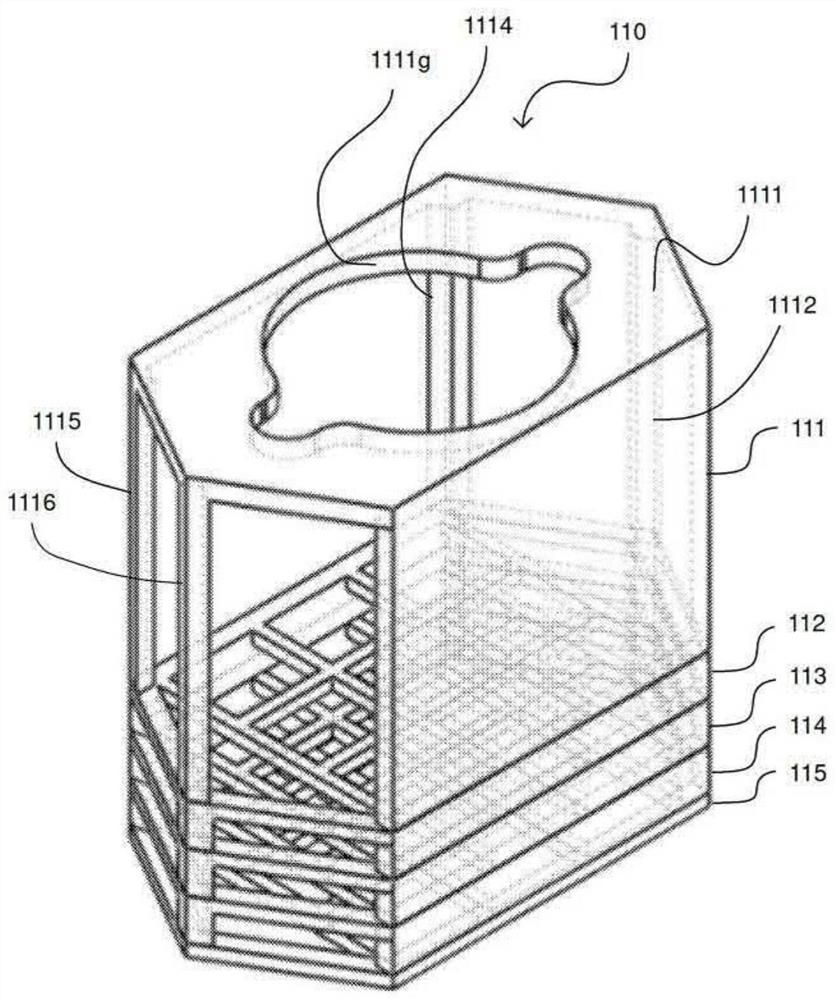
[0035] The filter device 11 has a support portion 110 and a filter 116 supported on the support portion 110 (refer to Figure 5 ). The support portion 110 has a plurality of stepped portions 112 to 115 stacked thereunder. The ...


PUM


Abstract

A gas flow meter (100) is provided with a filter device (11) having, on the upstream side of a flow rate measurement unit (121), a filter (113) for removing dust from gas flowing in from an inflow opening (101a), the filter (113) being disposed so as to cover the inflow opening (101a). At least a part of the filter (113) forms a plurality of layers of filter partition walls (1161-1164) arranged atintervals toward the downstream side, and at least two of the plurality of layers of filter partition walls (1161-1164) have openings at different positions toward the downstream side.

Description

technical field [0001] The invention relates to a gas flow meter. Background technique [0002] Currently, there is a proposal for a gas flow meter provided with a filter for trapping dust in gas. Figure 10A and Figure 10B These are diagrams schematically showing the internal structures of conventional gas flowmeters 200 and 300 , respectively. A flow measurement unit 203 ( 303 ) incorporating a flow sensor is arranged in a gas flow meter 200 ( 300 ) having an inlet 201 ( 301 ) and an outlet 202 ( 302 ). The inlet 201 (301) is provided with a stop valve 204 (304) for blocking the flow of gas into the gas flowmeter 200 (300). A filter 205 (305) is provided on the downstream side of the stop valve 204 (304). exist Figure 10A In this method, a bag-shaped filter 205 having a side surface along the inner wall of the gas flowmeter and a bottom surface that blocks the direction of the flow path is used. In addition, in Figure 10B In this case, the filter 305 arranged in th...

Claims


Application Information

Patent Timeline
IPC IPC(8): G01F15/12G01F15/00G01F15/08
CPCG01F15/125G01F15/005G01F15/08G01F1/6888B01D39/1692G01D4/02
Inventor 中尾秀之山本克行铃村宜晓龟井诚
Owner ORMON CORP
Features
  • R&D
  • Intellectual Property
  • Life Sciences
  • Materials
  • Tech Scout
  • Unparalleled Data Quality
  • Higher Quality Content
  • 60% Fewer Hallucinations
Learn More