Efficient combined cycle power plant with CO2 capture and a combustor arrangement with separate flows

a combined cycle power plant and flow-based technology, which is applied in the direction of machines/engines, mechanical equipment, separation processes, etc., can solve the problems of significant energy consumption, reduced efficiency of approximately 20% for a standard gas power plant producing electricity, and high investment cost and running cos

Active Publication Date: 2009-02-17
STATOIL ASA PETRO SA (NO)
View PDF10 Cites 101 Cited by
  • Summary
  • Abstract
  • Description
  • Claims
  • Application Information

AI Technical Summary

Benefits of technology

[0019]An object of the invention is to provide a power plant from which emission of climate gases and detrimental gases from an environmental point of view, such as amines, salts, etc. is reduced to a minimum or eliminated.
[0020]Another object is to obtain more energy- and cost effective solutions and to reduce, preferably bisect, both costs of investment and cost of operation compared to state of art technology. It is of particular interest to arrive at energy effective solutions in which the temperature at the inlet of the turbine is as high as possible. In addition a favourable and improved heat transfer in the combustor is obtained, hence transferring the high-quality heat energy to that part of the gas stream which is led to the turbine.
[0024]Further, a more simplified plant, not requiring large areas or footprints compared to the prior art amine washing solutions, is achieved, mainly since the CO2 membrane has a simplified construction and is not dependent upon a washing unit for separating CO2 from the liquid. An effective exploitation of such CO2 membrane solution, for example of the polymer type, for cleaning of flue gas requires that the flue gas both is pressurized and is enriched of CO2.
[0025]A further advantage according to the invention is that the need for large gas-gas heat exchangers may be reduced or completely eliminated. It may be difficult to construct such large heat exchangers for temperatures exceeding 600 C.° without using cost extensive solutions and expensive materials.
[0030]It is feasible to employ a semi-closed gas turbine cycle and a high CO2 content, since the combustor may receive both compressed air and recycled flue gas, thereby achieving stable combustion of natural gas.

Problems solved by technology

The regeneration process requires substantial amount of energy, resulting in a reduction in efficiency of approximately 20% for a standard gas power plant producing electricity.
A standard gas power plant having this type of exhaust gas cleaning means has thus the disadvantage that both investment costs and running costs are significantly high.
In addition, such plants require large areas.

Method used


Image

  • Efficient combined cycle power plant with CO2 capture and a combustor arrangement with separate flows
  • Efficient combined cycle power plant with CO2 capture and a combustor arrangement with separate flows
  • Efficient combined cycle power plant with CO2 capture and a combustor arrangement with separate flows

Examples


Embodiment Construction

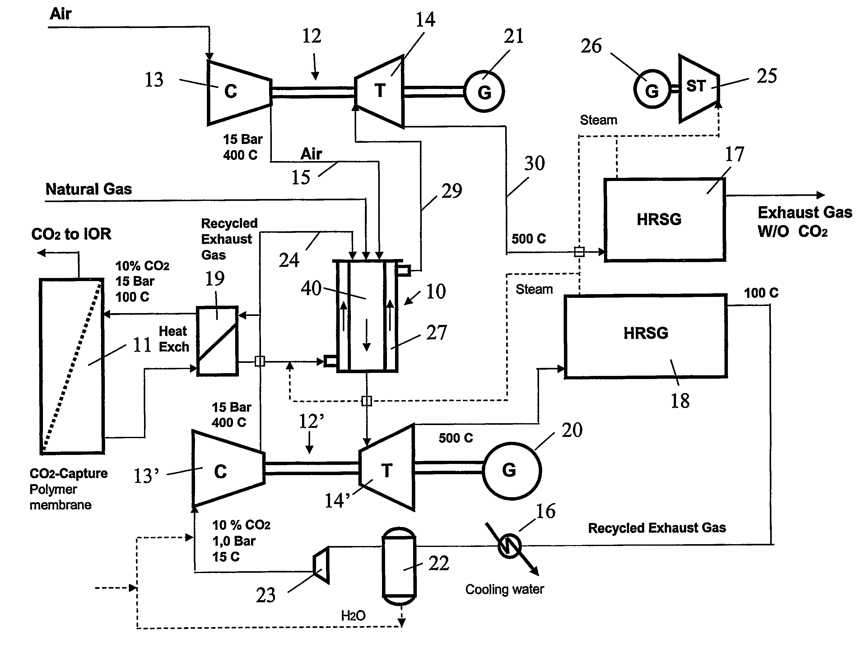
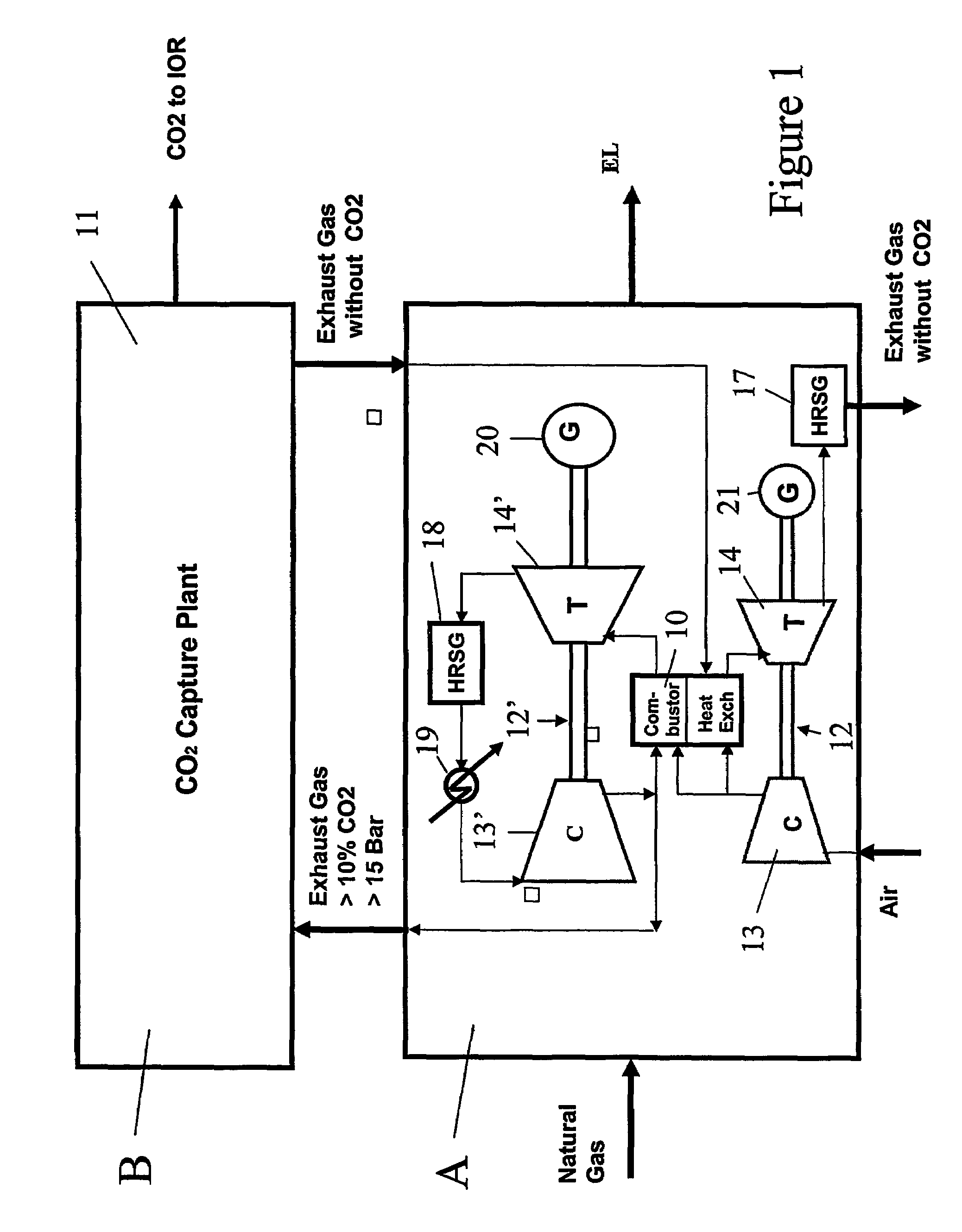
[0037]The process shown in principle and in a schematic manner in FIG. 1 comprises a gas power plant or a thermal power plant based in principle on a power plant part A in the form of a combined cycle gas turbine plant and an integrated CO2 capture plant B, for example a CO2 membrane plant 11 intended to separate CO2 from pressurized flue gas having CO2 enriched content, delivered from the combustor 10. The CO2 capture plant 11 may be of the amine system type.

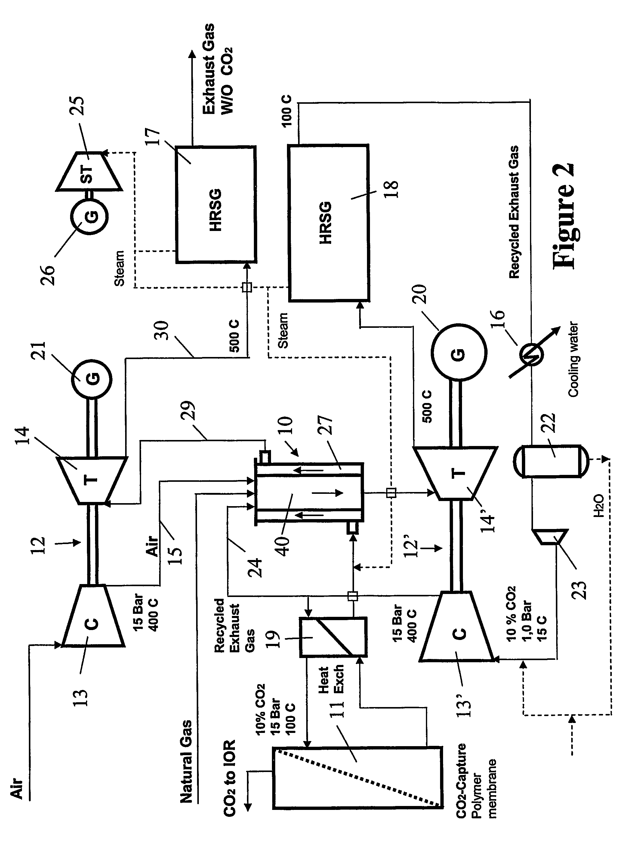
[0038]Two integrated gas turbine plants 12,12′ are used, depending on common combustor(s) 10 and operating in principle with two separate gas streams, one gas stream consisting of un-purified flue gas and one stream consisting inter alia of purified flue gas. The gas turbine plant 12′ may for example be of the semi-closed type. The combustor 10 comprises a flame tube 40 and a surrounding casing or jacket 27. The combustor 10 and its manner of operation will be described in further detail referring to FIGS. 2-4.

[0039]One or more...


PUM


Abstract

The invention relates to a method for inter alia to increase the energy and cost efficiency of a gas power plant or a thermal heat plant with CO2 capturing. The power plant comprises gas turbine plants (12,12′) comprising compressor units (13,13′) and turbine units (14,14′) and further comprises a combustor (10). The combustor (10) is working in principle with to separate gas part streams where one gas part stream flows internally through the flame tube (40) of the combustor (10), while the other gas part stream is flowing along the exterior of the flame tube (40). The first gas part stream comprises additional air and re-circulated, un-cleaned flue gas from the combustor (10), said gases being combusted together with fuel inside the flame tube (40). The second gas part stream comprises cleaned flue gas which is heated up at the exterior of the flame tube (40) while the flame tube (40) is cooled down. The invention comprises also a power plant, a combustor and a CO2 capture plant.

Description

CROSS-REFERENCE TO RELATED PATENT APPLICATIONS[0001]Norway Priority Application 2003 0682, filed Feb. 11, 2003 including the specification, drawings, claims and abstract, is incorporated herein by reference in its entirety. Norway Priority Application No. 20031550, filed Apr. 4, 2003 including the specification, drawings, claims and abstract, is incorporated herein by reference in its entirety. This application is a National Stage of U.S. Application PCT / NO2004 / 000036, filed Feb. 9, 2004, incorporated herein by reference in its entirety.FIELD OF INVENTION[0002]The present invention relates generally to a method for increasing the energy and cost efficiency of a gas power plant or a thermal power plant with a plant for CO2 capture. The invention relates further to a gas power plant or a thermal power plant. In particular the invention relates to integration of one or more combined cycle gas turbines and a CO2 exhaust gas cleaning plant, adapted to pressurized flue gas with enriched C...

Claims


Application Information

Patent Timeline
Patent Type & Authority Patents(United States)
IPC IPC(8): F02C1/00F02C3/30F02C7/08F02C7/12B01D53/62F01K23/10F02C3/34
CPCB01D53/62F01K23/10F02C3/34Y02E20/16Y02C10/04Y02A50/20Y02C20/40Y02E20/32
Inventor LYNGHJEM, ARNEJAKOBSEN, JONKOBRO, HENRIKLUND, ARNFINN
Owner STATOIL ASA PETRO SA (NO)
Why Eureka
Try Eureka