
Under-screen camera shooting assembly, camera shooting module, optical lens and manufacturing method thereof

An optical lens and manufacturing method technology, applied in optics, optical components, electrical components, etc., can solve problems such as affecting the screen experience, poor screen display effect, etc., to reduce space, improve imaging quality, and reduce lens volume Effect

Pending Publication Date: 2021-03-05
NINGBO SUNNY OPOTECH CO LTD
View PDF0 Cites 2 Cited by
  • Summary
  • Abstract
  • Description
  • Claims
  • Application Information

AI Technical Summary

Problems solved by technology

However, the size of the head of the current camera module is more than 3mm. Putting the head of the camera module into the hole will make the size of the screen opening large enough, and the camera module is placed behind the screen. To meet the requirements of the field of view, the side wall of the screen opening cannot affect the camera module to collect light, so the same opening should be relatively large, at least 4.5mm or more
Such a large opening will lead to poor display effect of the screen and affect the user experience of the screen

Method used


Image

  • Under-screen camera shooting assembly, camera shooting module, optical lens and manufacturing method thereof
  • Under-screen camera shooting assembly, camera shooting module, optical lens and manufacturing method thereof
  • Under-screen camera shooting assembly, camera shooting module, optical lens and manufacturing method thereof

Examples


Embodiment Construction

[0062] For a better understanding of the application, various aspects of the application will be described in more detail with reference to the accompanying drawings. It should be understood that these detailed descriptions are descriptions of exemplary embodiments of the application only, and are not intended to limit the scope of the application in any way. Throughout the specification, the same reference numerals refer to the same elements. The expression "and / or" includes any and all combinations of one or more of the associated listed items.

[0063] It should be noted that in this specification, expressions of first, second, etc. are only used to distinguish one feature from another, and do not represent any limitation on the features. Accordingly, a first body discussed hereinafter may also be referred to as a second body without departing from the teachings of the present application.

[0064] In the drawings, the thickness, size and shape of objects have been slight...


PUM

PropertyMeasurementUnit
Diameteraaaaaaaaaa
Diameteraaaaaaaaaa
Heightaaaaaaaaaa

Abstract

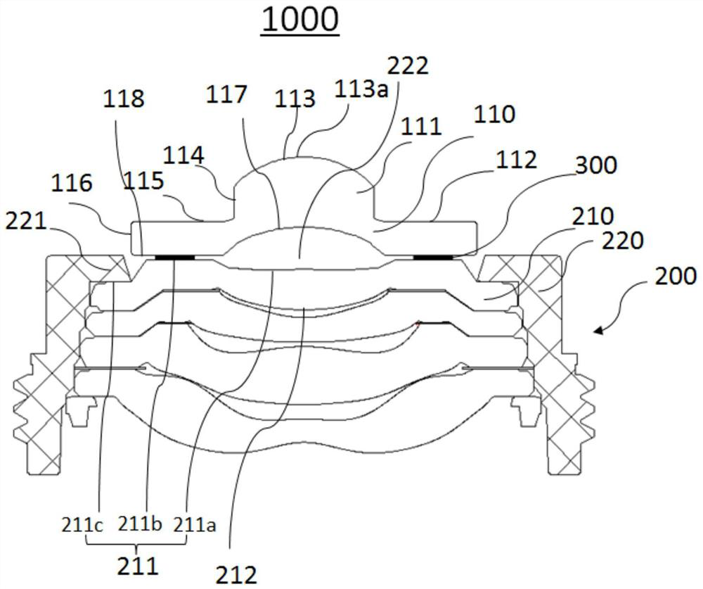
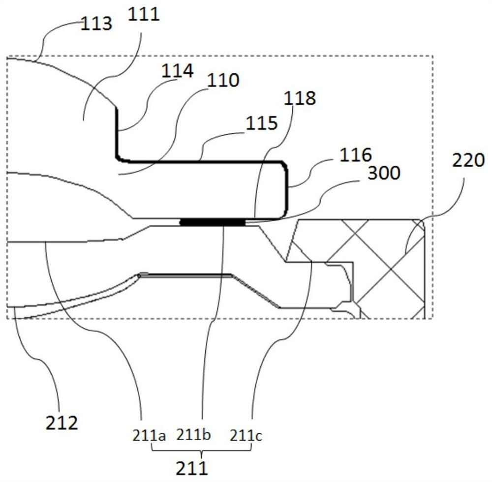
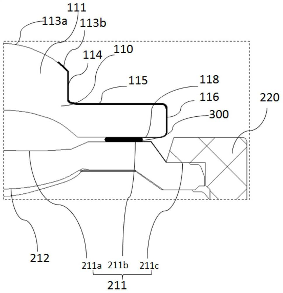
The invention relates to an optical lens. The optical lens comprises a first lens piece and a second lens part, the central area of the first surface of the first lens piece protrudes towards the object side to form a protruding part, the top surface of the first lens forms an optical area, and the first structure area surrounds the protruding part. The second lens part comprises a second lens barrel and at least one second lens piece, the top of the second lens barrel is provided with an extending part formed by extending inwards, the extending part forms a light inlet hole of the second lenspart, and the second lens piece at the topmost part is provided with a third surface located on the object side, and comprises an optical area located in the center, an inner structural area and an outer structural area, the inner structural area and the outer structural area surround the optical area, the outer structural area leans against the bottom surface of the extending part, and the innerstructural area is exposed outside the extending part. The first lens piece is bonded with the second lens part, and the outer diameter of the first lens piece is not larger than the aperture of thelight inlet hole. The invention further provides a corresponding camera shooting module, an under-screen camera shooting assembly and a corresponding manufacturing method. The aperture of the screen opening can be reduced on the premise of not sacrificing the imaging quality.

Description

technical field [0001] The invention relates to the technical field of camera modules, in particular, the invention relates to an under-display camera module, a corresponding camera module, an optical lens and a manufacturing method thereof. Background technique [0002] With the popularization of mobile electronic devices, related technologies of camera modules used in mobile electronic devices to help users acquire images (such as video or images) have developed rapidly and improved rapidly, and in recent years, camera modules Groups have been widely used in many fields such as medical treatment, security, industrial production and so on. [0003] In the field of consumer electronics, such as the field of smart phones, the front camera module is an indispensable component. The front camera module is usually arranged on the same side of the display screen, and is used for Selfie and other functions of the user. However, as the screen-to-body ratio increases, higher and hi...

Claims


Application Information

Patent Timeline
IPC IPC(8): G02B13/00G02B7/02G09F9/00H04N5/225G03B30/00
CPCG02B13/0015G02B13/0055G02B13/006G02B7/025G09F9/00G02B13/002H04N23/55
Inventor 裴海鹏梅哲文田中武彦
Owner NINGBO SUNNY OPOTECH CO LTD
Learn More