Supercharge Your Innovation With Domain-Expert AI Agents!

Object recognization method and device

An object recognition and object technology, applied in the field of image processing, can solve the problem of inaccurate recognition results, and achieve the effect of accurate recognition results

Pending Publication Date: 2021-03-05
HUAWEI TECH CO LTD
View PDF0 Cites 0 Cited by
  • Summary
  • Abstract
  • Description
  • Claims
  • Application Information

AI Technical Summary

Problems solved by technology

[0005] In order to solve the problem of inaccurate object recognition results, this application provides an object recognition method and device

Method used


Image

  • Object recognization method and device
  • Object recognization method and device
  • Object recognization method and device

Examples


Embodiment Construction

[0032] In order to make the purpose, technical solution and advantages of the present application clearer, the implementation manners of the present application will be further described in detail below in conjunction with the accompanying drawings.

[0033] In order to facilitate the understanding of the embodiments of the present application, the concepts of the nouns involved are firstly introduced below:

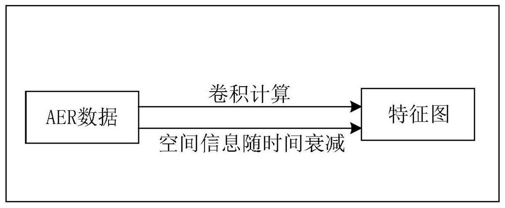
[0034]AER sensors, neuromorphic devices that mimic the mechanisms of the human retina. An AER sensor includes multiple pixels, each of which monitors changes in light intensity in a specific area. When the change exceeds the threshold, the AER event corresponding to the pixel is recorded, and when the change does not exceed the threshold, the AER event corresponding to the pixel is not recorded. Each AER event includes the location information (that is, address information) of the pixel where the AER event occurred, the time of occurrence (that is, the timestamp) and th...


PUM


Abstract

The invention provides an object recognization method, and belongs to the technical field of image processing. The method comprises the steps that when an object is recognized in AER data, the AER data of the to-be-recognized object can be obtained, the AER data comprises multiple AER events of the to-be-recognized object, each AER event comprises a timestamp and address information for generatingthe AER event, multiple feature maps of the AER data are extracted, and each feature map comprises partial space information and partial time information of the to-be-recognized object; wherein the partial space information and the partial time information are obtained according to the timestamp and the address information of each AER event, and identifying the to-be-identified object according to the plurality of feature maps of the AER data. According to the invention, the accuracy of the object recognition result can be improved.

Description

technical field [0001] The present application relates to the technical field of image processing, in particular to an object recognition method and device. Background technique [0002] Traditional vision sensors use "frame scanning" as the image acquisition method. With the improvement of performance requirements such as speed in the practical application of vision systems, traditional vision sensors have encountered development bottlenecks such as excessive data and limited frame rates. The address event representation (AER) sensor based on the bionic visual perception model has become a research hotspot in the field of machine vision systems due to its advantages of high speed, low delay, and low redundancy. Each pixel in the AER sensor monitors the relative change of the light intensity in a specific area respectively. If the change exceeds a predefined threshold, the AER event corresponding to the pixel is recorded. The AER event includes the position of the pixel (tha...

Claims


Application Information

Patent Timeline
IPC IPC(8): G06K9/46G06K9/62
CPCG06V10/454G06F18/214G06V10/62G06V10/77G06N3/049G06N3/088G06N3/045
Inventor 潘纲刘千惠蒋磊程捷阮海博邢东唐华锦马德
Owner HUAWEI TECH CO LTD
Features
  • R&D
  • Intellectual Property
  • Life Sciences
  • Materials
  • Tech Scout
  • Unparalleled Data Quality
  • Higher Quality Content
  • 60% Fewer Hallucinations
Learn More