Threaded hole and through hole centering alignment method for vehicle tool production and assembly
A threaded hole and tool technology, which is applied in the field of alignment of threaded holes and through holes in the production and assembly of vehicle tools, can solve problems such as difficulty in adapting to automated production and low efficiency, and achieve convenient alignment adjustment, high automation level, and production. Efficient effect
- Summary
- Abstract
- Description
- Claims
- Application Information
AI Technical Summary
Problems solved by technology
Method used
Image

Examples
Embodiment Construction
[0031] In order to make the objects and advantages of the present invention clearer, the present invention will be described in detail below in conjunction with the examples. It should be understood that the following words are only used to describe one or several specific implementation modes of the present invention, and do not strictly limit the protection scope of the specific claims of the present invention.
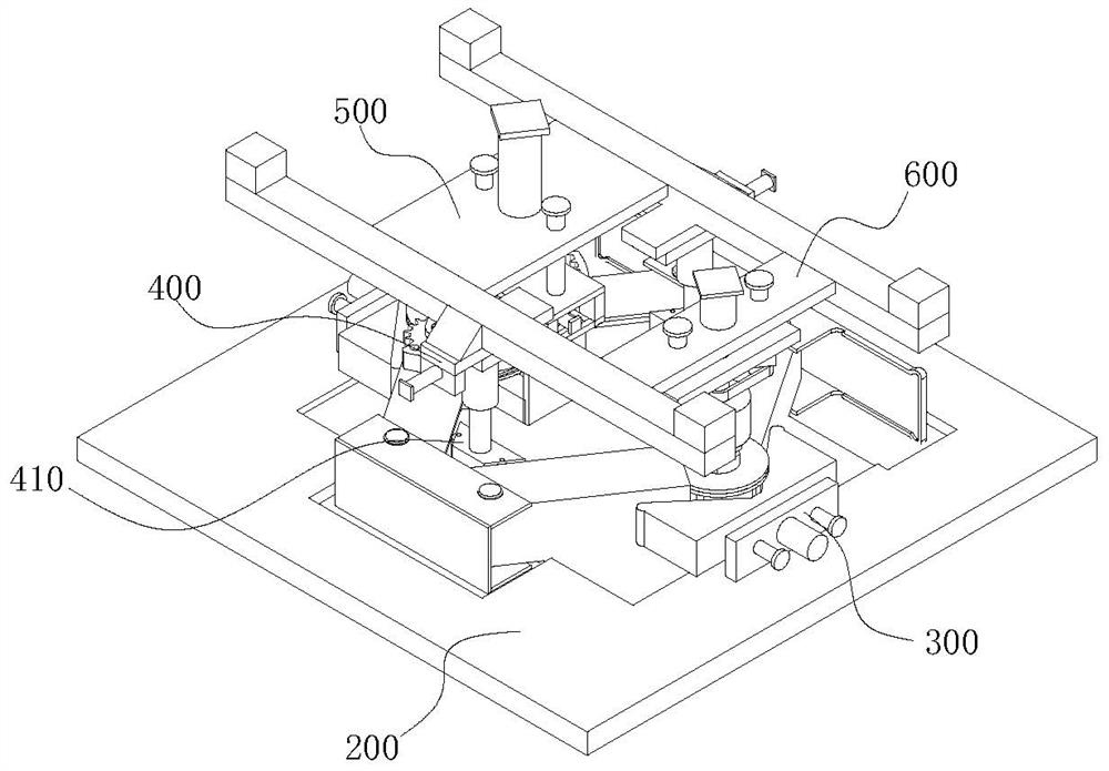
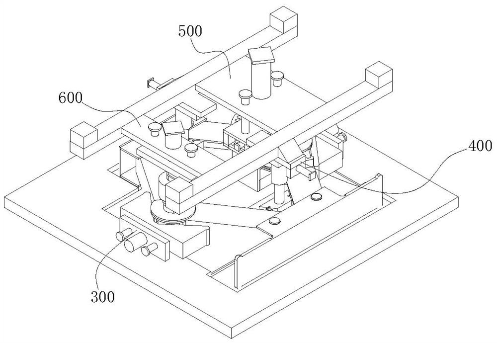
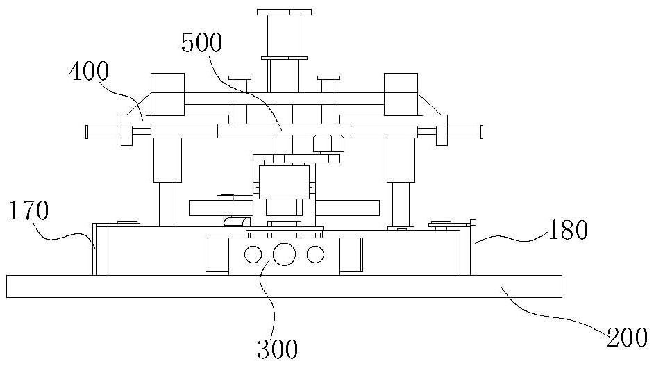
[0032] refer to Figure 1 to Figure 13 , the embodiment of this application proposes a device for aligning the threaded hole and the through hole on the body of the jack support frame, aiming to solve the problem in the prior art that during the process of assembling the jack, the A installation shaft The alignment between the center line of the threaded hole and the through hole on the B installation shaft requires manual concentric alignment, which leads to problems such as low efficiency of production assembly.
[0033] Such as Figure 13 As shown, the upper br...
PUM
 Abstract
Description
Claims
Application Information
 - R&D
- Intellectual Property
- Life Sciences
- Materials
- Tech Scout
- Unparalleled Data Quality
- Higher Quality Content
- 60% Fewer Hallucinations
Browse by: Latest US Patents, China's latest patents, Technical Efficacy Thesaurus, Application Domain, Technology Topic, Popular Technical Reports.
© 2025 PatSnap. All rights reserved.Legal|Privacy policy|Modern Slavery Act Transparency Statement|Sitemap|About US| Contact US: help@patsnap.com