Mold assembly

A component and mold technology, applied in the field of mold components, can solve problems such as insufficient spring compression space, and achieve the effect of solving poor product appearance

Pending Publication Date: 2021-03-09
WENZHOU HTM MOLD DEV
View PDF0 Cites 0 Cited by
  • Summary
  • Abstract
  • Description
  • Claims
  • Application Information

AI Technical Summary

Problems solved by technology

[0003] Purpose of the present invention: In order to overcome the defects of the prior art, the present invention provides a mold assembly, adding a spring sleeve to utilize the space of the push plate, which solves the problem of insufficient spring compression space, without changing the plate thickness and In the case of mold height, increase the compression space of the spring

Method used


Image

  • Mold assembly
  • Mold assembly
  • Mold assembly

Examples


Embodiment Construction

[0023] The specific embodiment of the present invention is described in detail below in conjunction with accompanying drawing:

[0024] The big mouth end in this article refers to the end of the longer base of the trapezoid, and does not have other special meanings.

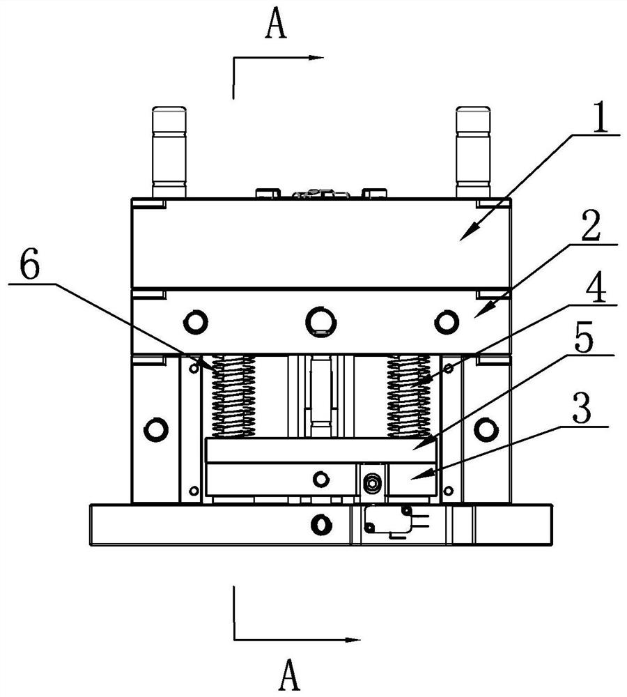
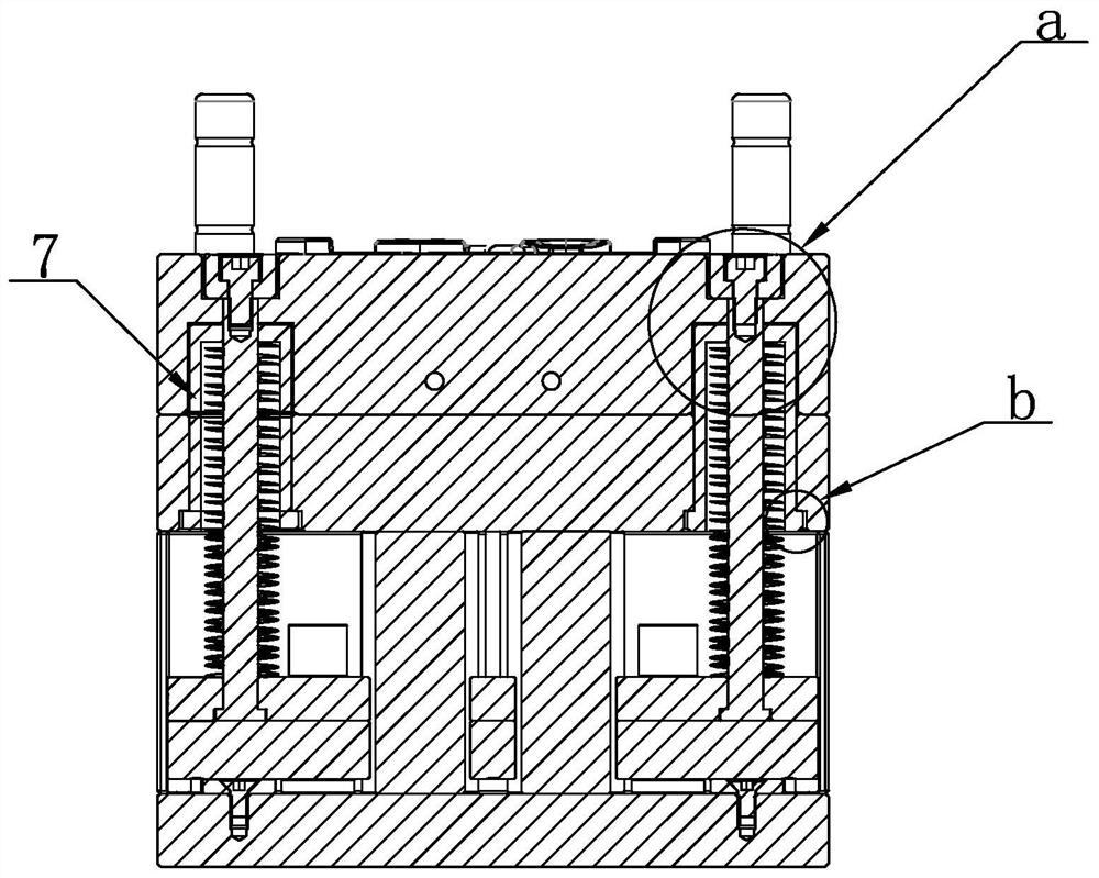
[0025] The disclosure of the present invention relates to a mold assembly, comprising a push plate 1, a template 2, a thimble base plate 3 and a thimble panel 5 equipped with a thimble 4 arranged in sequence, and the thimble base plate 3 can drive the thimble panel 5 and the thimble 4 to move in the direction of the push plate 1 , the thimble 4 is linked with the push plate 1, and the thimble 4 is also covered with a spring 6. In the embodiment of the present invention, a spring sleeve 7 is also included, and the side of the push plate 1 facing the template 2 is provided with a cavity 111 , the spring sleeve 7 extends through the template 2 into the cavity 111, the top of the spring sleeve 7 is provided with a su...


PUM


Abstract

The invention discloses a mold assembly which comprises a push plate, a mold plate, an ejector pin bottom plate, an ejector pin panel provided with an ejector pin and a spring sleeve. The ejector pinis further sleeved with a spring, a supporting plate is arranged at the top of the spring sleeve, the ejector pin penetrates through the supporting plate to be connected with the push plate, and a limiting structure for limiting the spring sleeve from moving towards the push plate is arranged between the spring sleeve and the mold plate; a material pulling well is arranged on the push plate, protruding blocks are arranged on the inner side wall of the material pulling well, each protruding block is provided with a holding part, the spring sleeve is additionally arranged to utilize the space ofthe push plate, the problem that the compression space of the spring is insufficient is solved, the compression space of the spring is increased under the condition that the plate thickness and the mold height are not changed, the principle that plastic expands with heat and contracts with cold is utilized, after injection molding is finished, cold materials located at the positions of the holding parts in the material pulling well can form necking openings, and the necking openings shrink when being cooled, so that the necking openings and the holding parts shrink more and more tightly, theholding effect is achieved, static mold waste is brought out, and then the static mold waste is ejected out through the ejector pin and the push plate.

Description

technical field [0001] The invention relates to the technical field of molds, in particular to a mold assembly. Background technique [0002] In the mold design, springs are used in almost every pair of molds. When the spring is too long, the compression ratio of the spring becomes a very troublesome problem. After the mold is increased, the size of the injection molding machine is not enough, and a larger injection molding machine must be used. This not only wastes the cost of the mold, but also wastes energy in the injection molding process, which increases energy consumption and emissions; when some customers have their own injection molding machines, the mold is too high because the spring is too long, exceeding the size of the customer's injection molding machine. , the customer needs to purchase a larger injection molding machine, and the cost required at this time will be relatively high. Contents of the invention [0003] Purpose of the present invention: In order...

Claims


Application Information

Patent Timeline
Patent Type & Authority Applications(China)
IPC IPC(8): B29C45/40
CPCB29C45/4005B29C45/401
Inventor 郑荣芬聂莙林彭盛涨杜笑怜余立成
Owner WENZHOU HTM MOLD DEV
Why Eureka
Try Eureka