Vacuum pump control method and device

A control method and vacuum pump technology, applied in the direction of brake transmission, brake, transportation and packaging, etc., can solve the problems of vehicle brake safety hazards and other problems

Active Publication Date: 2021-03-09
DONGFENG MOTOR CORP HUBEI
View PDF6 Cites 0 Cited by
  • Summary
  • Abstract
  • Description
  • Claims
  • Application Information

AI Technical Summary

Problems solved by technology

[0005] Aiming at the problems existing in the prior art, the embodiment of the present invention provides a vacuum pump control method and device, which is used to solve the problem in the prior art that when the vehicle enters a high-altitude area, it cannot reach the maximum speed of the vehicle without increasing the cost. Excellent braking performance, leading to technical problems of vehicle braking safety hazards

Method used


Image

  • Vacuum pump control method and device
  • Vacuum pump control method and device

Examples


Embodiment 1

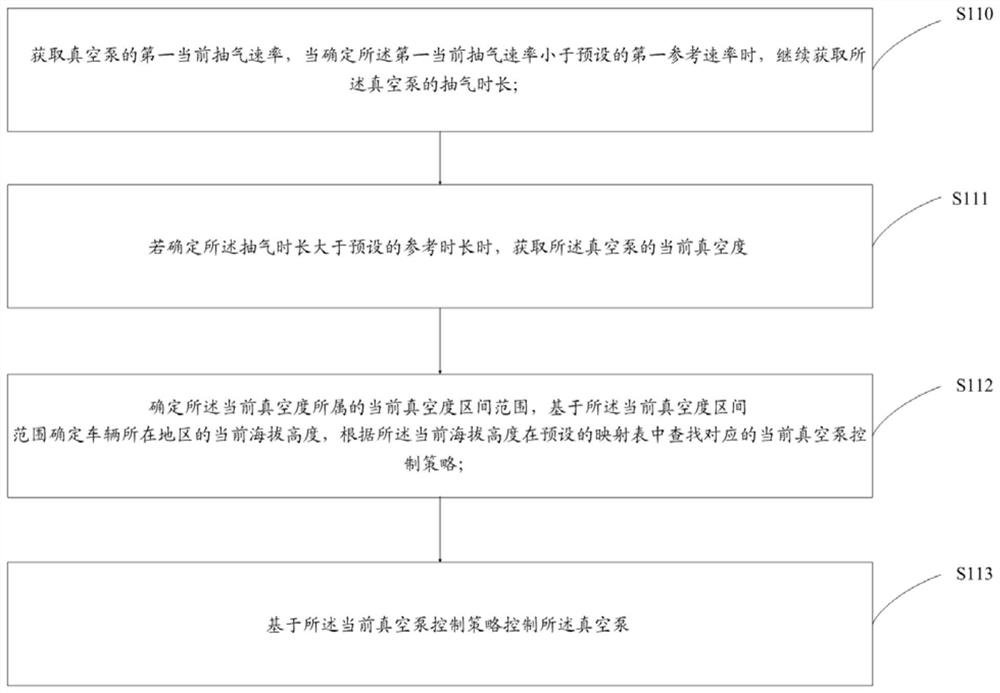
[0053] This embodiment provides a control method for a vacuum pump, such as figure 1 As shown, the methods include:

[0054] S110. Obtain the first current pumping rate of the vacuum pump. When it is determined that the first current pumping rate is less than the preset first reference rate, continue to obtain the pumping time of the vacuum pump; the first reference rate is the vehicle The minimum pumping rate of the vacuum pump in plain areas;

[0055] As the altitude increases, the atmospheric pressure decreases regularly, and the pumping rate of the vacuum pump also changes regularly. The average altitude increases by 1Km, and the atmospheric pressure decreases by about 10Kpa. Based on this, when the vehicle is running, obtain the first current pumping rate of the vacuum pump, and when it is determined that the first current pumping rate is less than the preset first reference rate, continue to obtain the pumping time of the vacuum pump, if the pumping time is less than or...

Embodiment 2

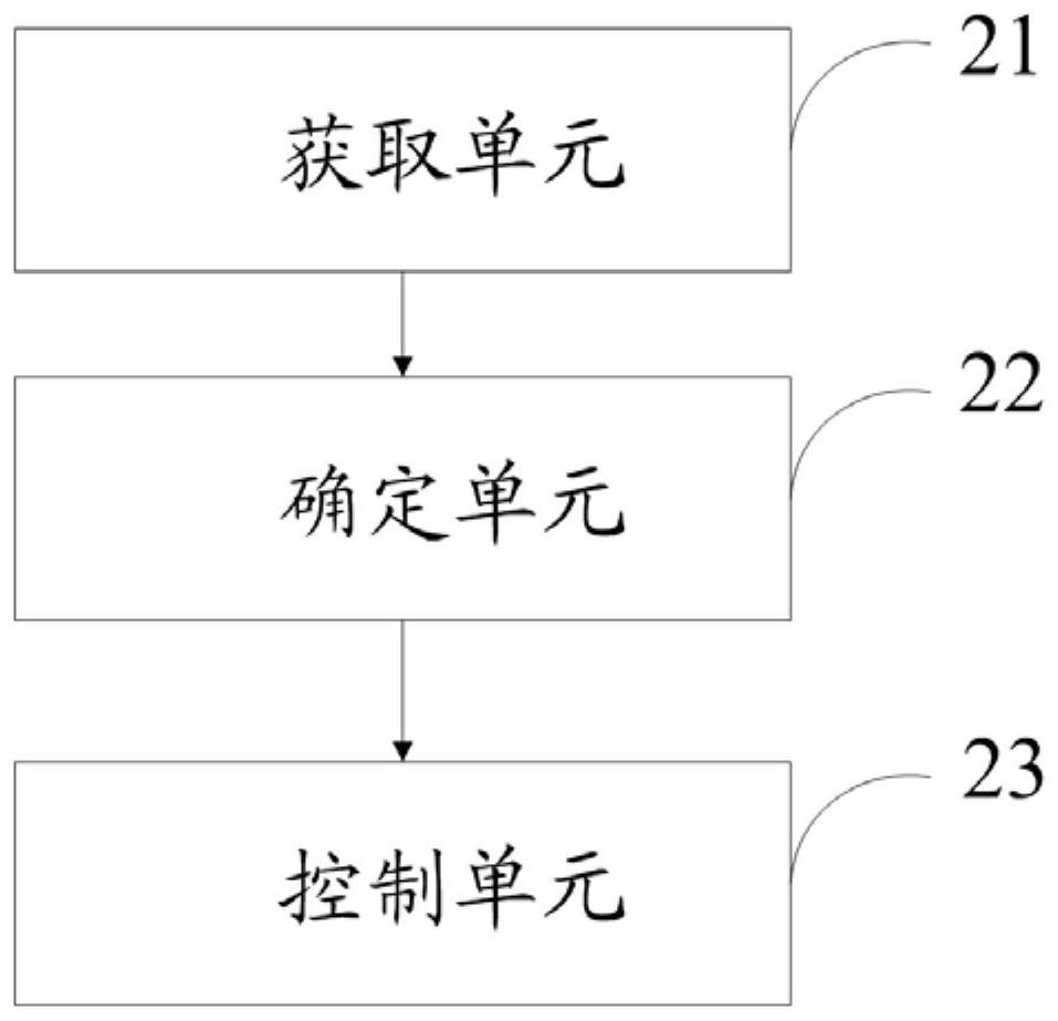
[0102] This embodiment provides a control device for a vacuum pump, such as figure 2 As shown, the device includes: an acquisition unit 21, a determination unit 22, and a control unit 23; wherein,

[0103] The acquiring unit 21 is configured to acquire a first current pumping rate of the vacuum pump, and when it is determined that the first current pumping rate is less than a preset first reference rate, continue to acquire the pumping time of the vacuum pump; the first The reference rate is the minimum pumping rate of the vacuum pump when the vehicle is in a plain area; if it is determined that the pumping time is longer than the preset reference time, the current vacuum degree of the vacuum pump is obtained;

[0104] The determining unit 22 is configured to determine the current vacuum degree range to which the current vacuum degree belongs, determine the current altitude of the area where the vehicle is located based on the current vacuum degree range, and determine the cu...


PUM


Abstract

The invention provides a vacuum pump control method and device, and the method comprises the steps: obtaining a first current air extraction rate of the vacuum pump, and obtaining the air extraction duration of the vacuum pump when the first current air extraction rate is determined to be smaller than a first reference rate; if it is determined that the air exhaust duration is longer than the reference duration, obtaining the current vacuum degree of a vacuum pump; determining a current vacuum degree interval range to which the current vacuum degree belongs, determining a current altitude of aregion where the vehicle is located based on the current vacuum degree interval range, and searching a corresponding current vacuum pump control strategy according to the current altitude; controlling the vacuum pump based on the current vacuum pump control strategy; thus, under the condition that the cost of the vehicle is not increased, the specific altitude of the area where the vehicle is located is accurately judged by detecting the pumping speed and the vacuum degree of the vacuum pump, and then the vacuum pump control strategy corresponding to the altitude is executed, so that the vehicle can achieve the optimal braking performance in plateau areas with different altitudes; and vehicle driving safety is ensured.

Description

technical field [0001] The invention belongs to the technical field of automobile control, and in particular relates to a control method and device of a vacuum pump. Background technique [0002] When a vehicle drives from a plain to a plateau, the pumping rate of a vehicle equipped with an electric vacuum pump will decrease due to the drop in air pressure. If the vacuum pump control strategy in the plain is maintained, the vacuum pump will continue to work. In this case, it is very easy Damage to the vacuum pump will bring safety hazards to the vehicle. [0003] In order to ensure that the vehicle can run normally on both plains and plateaus, vacuum pump strategies in plateau areas are generally set to deal with plateau conditions. There are two methods in the prior art: first, adding an atmospheric pressure sensor to the vehicle, and judging the altitude based on the data measured by the atmospheric pressure sensor to determine whether to implement the vacuum pump control...

Claims


Application Information

Patent Timeline
Patent Type & Authority Applications(China)
IPC IPC(8): B60T13/72B60T17/22
CPCB60T13/72B60T17/22
Inventor 王平徐小卫闫涛卫尹佳超陈世荣
Owner DONGFENG MOTOR CORP HUBEI
Why Eureka
Try Eureka