Sand casting die assembly

A molding device and sand foundry technology, which is applied to casting molding equipment, molding machines, manufacturing tools, etc., can solve the problems of difficult mold replacement, insufficient firmness of application, and complicated clamping of sand mold boxes, and achieve simple and firm clamping, Effects that increase the scope of application and facilitate movement

Active Publication Date: 2018-04-06
马鞍山市海华金属制品有限公司
View PDF5 Cites 26 Cited by
  • Summary
  • Abstract
  • Description
  • Claims
  • Application Information

AI Technical Summary

Problems solved by technology

[0003] The purpose of the present invention is to solve the defects in the prior art that the mold for foundry casting is not easy to replace after being damaged, the clamping of the sand mold box is complicated and not firm enough, and the scope of application is low, and a kind of foundry casting die device is proposed.

Method used


Image

  • Sand casting die assembly
  • Sand casting die assembly
  • Sand casting die assembly

Examples


Embodiment Construction

[0017] The following will clearly and completely describe the technical solutions in the embodiments of the present invention with reference to the accompanying drawings in the embodiments of the present invention. Obviously, the described embodiments are only some, not all, embodiments of the present invention.

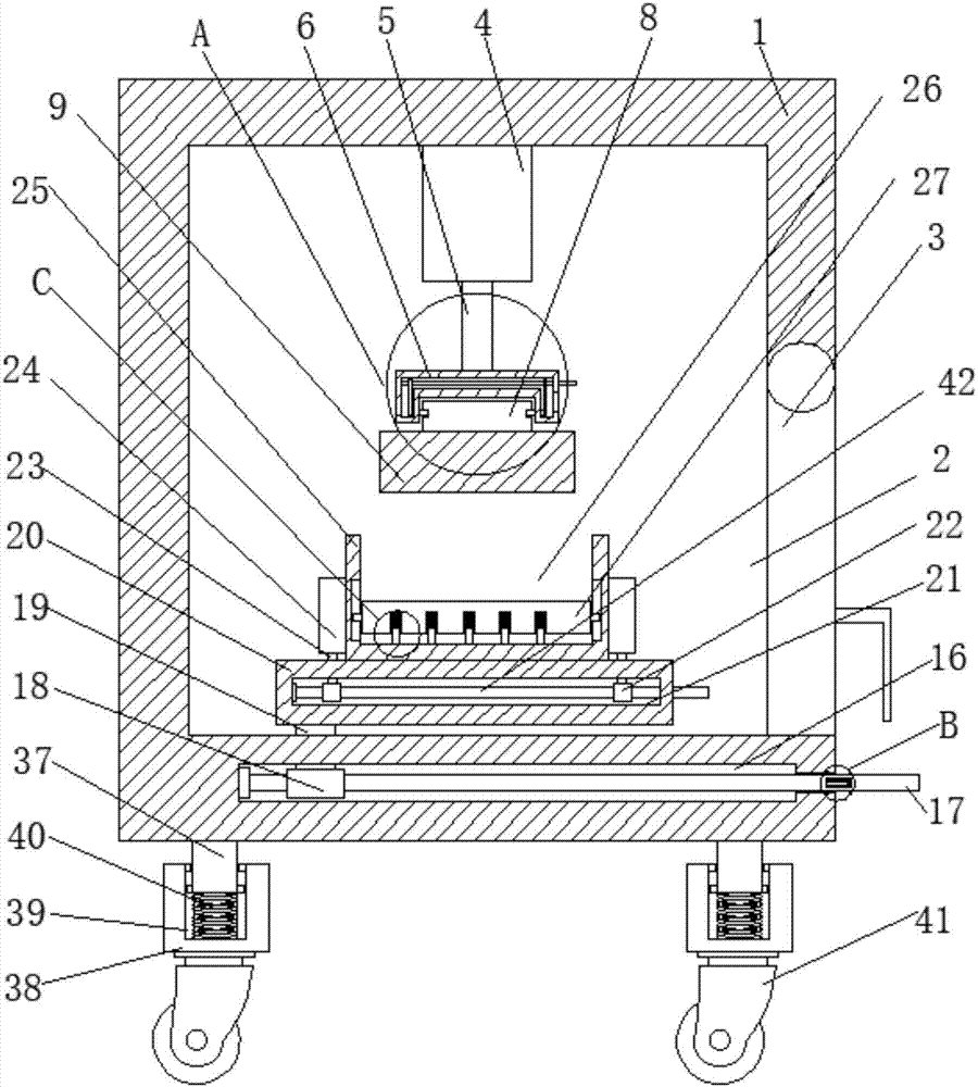
[0018] refer to Figure 1-4 , a sand foundry casting die device, comprising a housing 1, the housing 1 is hollow, the lower end of the housing 1 is also provided with a support column 37, the lower end of the support column 37 is also provided with a base 38, and the base 38 is also provided with A groove 39 with an upward opening, and the bottom of the groove 39 is connected to the support column 37 through the third spring 40. When the device is running, the vibration generated by the work is greatly weakened by the third spring 33 and then transmitted to the ground, which effectively weakens the vibration of the device. The noise pollution caused by vibration hitt...


PUM


Abstract

The invention discloses a sand casting die assembly comprising a shell which is of a hollow structure. One side wall of the shell is further provided with a feed port of which the opening position isrotatably connected to a cover plate, and the inner wall of the upper side of the shell is fixedly connected to a cylinder; the output end of the cylinder is connected to a piston rod, and the end, far away from the cylinder, of the piston rod is connected to a mounting plate of which the lower end is further provided with a die; the upper end of the die is provided with a mounting block, and thelower side wall of the mounting plate is provided with a mounting groove matched with the mounting block; the mounting plate is internally provide with two cavities arranged symmetrically, and the cavities are internally provided with first slide bars arranged vertically; the opposite side walls of the two first slide bars are both provided with first clamping blocks which penetrate the cavities;and the side wall of the mounting block is provided with a first slot matched with the first clamping blocks. According to the sand casting die assembly disclosed by the invention, a clamping sand mould is simple and firm, and the die for compression molding is easy to remove and displace; and the die assembly is wide in application scope.

Description

technical field [0001] The invention relates to the field of casting technology, in particular to a sand casting die device. Background technique [0002] The manufacturing process of foundry casting is generally to manufacture the sand mold for casting first, then inject the liquid casting material into the sand mold, take out the casting after cooling, arrange (remove the attached sand, arrange the injection hole) or clean, and the casting is completed. The existing molds for foundry casting are generally fixed on the die device, and it is not easy to replace after damage. The clamping of the sand box is complicated and not firm enough, and the scope of application of the device is relatively low; therefore, we propose a foundry Cast die devices are used to solve these problems. Contents of the invention [0003] The purpose of the present invention is to solve the defects in the prior art that the mold for foundry casting is not easy to replace after being damaged, the...

Claims


Application Information

Patent Timeline
Patent Type & Authority Applications(China)
IPC IPC(8): B22C17/00
CPCB22C17/00
Inventor 夏进
Owner 马鞍山市海华金属制品有限公司
Why Eureka
Try Eureka