
Spring bolt mechanism and lock

A lock tongue and moving plate technology, applied in the field of locks, can solve problems such as high resistance of the lock tongue structure, and achieve the effect of saving effort in unlocking

Pending Publication Date: 2021-03-09
SHANDONG WISDOM LIFE DATA SYST
View PDF0 Cites 0 Cited by
  • Summary
  • Abstract
  • Description
  • Claims
  • Application Information

AI Technical Summary

Problems solved by technology

[0004] The technical problem to be solved by the present invention is to provide a deadbolt mechanism and a lockset in view of the above-mentioned defects of the prior art, so as to overcome the defect that the existing deadbolt structure has relatively large resistance when unlocking.

Method used


Image

  • Spring bolt mechanism and lock
  • Spring bolt mechanism and lock
  • Spring bolt mechanism and lock

Examples


Embodiment Construction

[0022] The preferred embodiments of the present invention will now be described in detail with reference to the accompanying drawings.

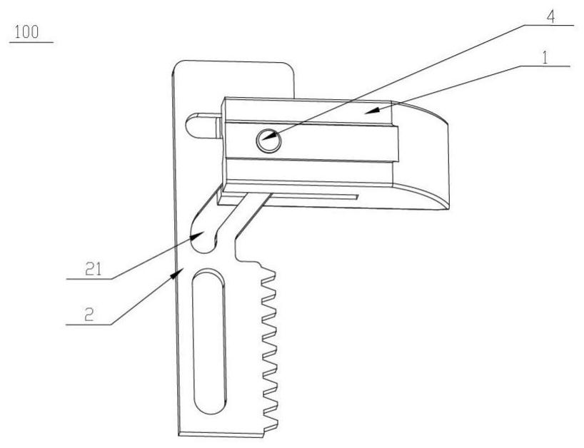
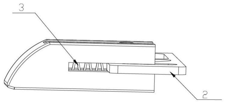
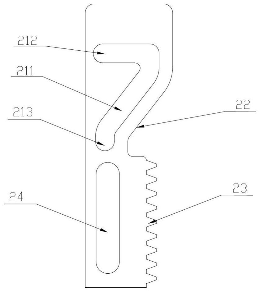
[0023] like Figure 1 to Figure 3 As shown, the deadbolt mechanism 100 of the present invention includes a deadbolt 1, a moving plate 2 and an elastic member 3. The locking tongue 1 can be telescopically moved, and a limiting member 4 is arranged on it. The moving plate 2 is provided with a sliding groove 21 , and the sliding groove 21 includes a first groove segment 211 inclined relative to the moving direction of the lock tongue 1 . The limiter 4 is inserted in the chute 21 to realize the linkage between the lock tongue 1 and the moving plate 2 . One side surface of the moving plate 2 is provided with a guiding inclined surface 22 which is parallel to the first groove section 211 or forms a small angle with the first groove section 211 . One end of the elastic member 3 is connected with the locking tongue 1 , and the other end is abutted...


PUM


Abstract

The invention relates to a spring bolt mechanism and a lock. The spring bolt mechanism comprises a spring bolt, a movable plate and an elastic piece; the spring bolt can move in a telescopic mode, anda limiting piece is arranged on the spring bolt; the movable plate is provided with a sliding groove, and the sliding groove comprises a first groove section which is obliquely arranged relative to the movable direction of the spring bolt; the limiting piece is arranged in the sliding groove in a penetrating mode, so that linkage of the spring bolt and the movable plate is achieved; a guide inclined plane parallel to the first groove section or forming a small included angle with the first groove section is arranged on one side surface of the movable plate; one end of the elastic piece is connected with the spring bolt, and the other end of the elastic piece abuts against the side face, provided with the guide inclined plane, of the movable plate; and when the movable plate moves to pushthe spring bolt to move in a telescopic mode, the limiting piece moves in the first groove section, and the end, abutting against the side face of the movable plate, of the elastic piece moves on theguide inclined plane. In the whole locking and unlocking process, the elastic piece does not deform or deforms little, so that when the spring bolt contracts for unlocking, only the friction force between the spring bolt and a lock hole needs to be overcome, unlocking can be achieved without large torsion, and labor is saved during unlocking.

Description

technical field [0001] The invention relates to the technical field of locks, in particular to a latch mechanism and a lock. Background technique [0002] With the continuous advancement of technology, various forms of locks have appeared in life, including combination locks and fingerprint locks. Among them, a combination lock is an electronic product that controls the operation of a circuit or a chip (access control system) through the input of a password, thereby controlling the closing of a mechanical switch and completing the task of unlocking and locking. There are many types of it, including simple circuit products and cost-effective products based on chips. Now the widely used electronic combination lock is based on the chip and realized by programming. Electronic locks In the field of security technology prevention, electronic combination locks with anti-theft alarm function replace traditional mechanical combination locks, overcoming the shortcomings of mechanica...

Claims


Application Information

Patent Timeline
IPC IPC(8): E05B15/10E05B15/00E05B47/00
CPCE05B15/00E05B15/101E05B47/0012E05B47/026
Inventor 袁雅昆杜贵阳庞旭
Owner SHANDONG WISDOM LIFE DATA SYST
Learn More