Check patentability & draft patents in minutes with Patsnap Eureka AI!

Power grid current sensor connection identification detection method

A technology of current sensor and grid current, applied in the direction of electrical connection test, instrument, measuring device, etc., can solve the problems of CT not working normally and connection error

Active Publication Date: 2021-03-09
SOLAR POWER NETWORK TECHNOLOGY (ZHEJIANG) CO LTD
View PDF9 Cites 2 Cited by
  • Summary
  • Abstract
  • Description
  • Claims
  • Application Information

AI Technical Summary

Problems solved by technology

Because there are many places to pay attention to when connecting CT, users generally only rely on the records in the manual or experience to install during the installation process, and it is easy to make connection errors, which will cause CT to fail to work normally.
In the existing technology, there is no method that can accurately identify the CT connection mode

Method used


Image

  • Power grid current sensor connection identification detection method
  • Power grid current sensor connection identification detection method

Examples


Embodiment

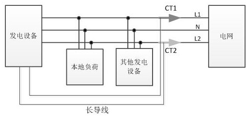
[0024] Such as figure 1 As shown, CT1 and CT2 are used to collect the current at the network end, CT1 and CT2 are prone to wrong connection, for example, the direction of CT1 is reversed, CT1 and CT2 are interchanged, CT1 or CT2 is not fastened, cannot be sampled, etc., so Identification testing is required.

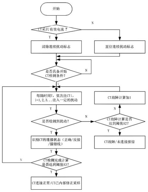
[0025] Such as figure 2 As shown, a connection identification and detection method of a grid current sensor includes the following steps:

[0026] Step 1, current sampling:

[0027] First, detect the sampling current of N current sensors in the circuit. If the CT collects effective current, it is considered that the CT has not been disassembled and installed, and the continuous disturbance flag is cleared, and a CT cycle detection is performed on the CT. Because the external load is relatively complex, it is possible that the disturbance collected by CT is caused by the user switching load, so a CT cycle detection requires several rounds of disturbance detection to d...


PUM


Abstract

The invention discloses a power grid current sensor connection identification detection method comprising the following steps: 1, CT cycle detection: carrying out CT cycle detection for several timeson N current sensors in a circuit, each CT cycle detection is to carry out several rounds of disturbance detection in a power grid specified detection time, and each round of disturbance detection comprises: at an interval of time T, applying disturbance once to the power connecting lines where the N current sensors are located in sequence; 2, sampling feedback: identifying the connection state ofthe current sensor according to the sampling result of the current sensor after each CT cyclic detection; and 3, processing and warning: according to the determined connection state of the current sensor, automatically processing a feedback sampling value through the controller, and correcting the sampling value to a correct sampling amount or giving an alarm, so that the current sensor can alsowork normally when the current sensor is connected wrongly. The method has the advantages that the CT connection mode is recognized and corrected, and it is guaranteed that normal work can also be achieved when CT wrong connection is conducted.

Description

technical field [0001] The invention relates to a circuit connection identification method, in particular to a connection identification detection method of a grid current sensor. Background technique [0002] In order to meet the limit requirements of grid input power, the power generation equipment needs to collect the current at the interface of the user grid through the current sensor (CT), and calculate and control its own grid input power in real time. At present, the common CT is an openable circular ring structure, which is convenient for users to install to the grid entry end by themselves. In order to collect the current correctly, the installation of the CT needs to pay attention to the orientation of the torus, otherwise the reverse current is likely to be collected. In addition, for a single-phase three-wire or three-phase three-wire power grid, multiple CTs need to be connected to corresponding multiple lines. Since there are many places to pay attention to w...

Claims


Application Information

Patent Timeline
IPC IPC(8): G01R31/66G01R35/02
CPCG01R35/02G01R31/66
Inventor 魏琪康郭华为施鑫淼刘超厚李新富
Owner SOLAR POWER NETWORK TECHNOLOGY (ZHEJIANG) CO LTD
Features
  • R&D
  • Intellectual Property
  • Life Sciences
  • Materials
  • Tech Scout
  • Unparalleled Data Quality
  • Higher Quality Content
  • 60% Fewer Hallucinations
Learn More