Cable bridge

A technology for cable trays and side panels, applied in the direction of electrical components, etc., can solve the problems of inconvenient use of cable trays, and achieve the effects of enhanced fixing strength, enhanced heat dissipation effect, and convenient use

Pending Publication Date: 2021-03-09
国网河南省电力公司新县供电公司
View PDF1 Cites 2 Cited by
  • Summary
  • Abstract
  • Description
  • Claims
  • Application Information

AI Technical Summary

Problems solved by technology

[0004] In order to solve the above-mentioned technical problems, the object of the present invention is to provide a cable tray to solve the technical problem of inconvenient use of the cable tray in the prior art

Method used


Image

  • Cable bridge
  • Cable bridge
  • Cable bridge

Examples


Embodiment Construction

[0024] The specific implementation manners of the present invention will be further described in detail below in conjunction with the accompanying drawings and embodiments. The following examples are used to illustrate the present invention, but are not intended to limit the scope of the present invention.

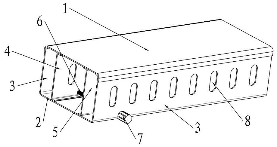
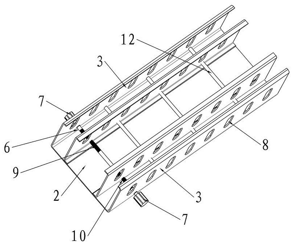
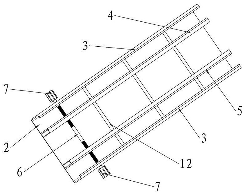
[0025] The specific embodiment of the cable tray of the present invention, such as Figure 1 to Figure 4 As shown, it includes a bottom plate 2 and two side plates 3 , and the two side plates 3 are fixedly connected to both ends of the bottom plate 2 in the width direction. The bottom plate 2 and the two side plates 3 enclose a wire groove for laying cables.

[0026] In this embodiment, the bottom plate 2 is provided with a first partition 4 and a second partition 5 , and the first partition 4 and the second partition 5 are located between the two side plates 3 . Both the first partition 4 and the second partition 5 extend along the length direction of the trunking, and ...


PUM


Abstract

The invention relates to a cable bridge. The cable bridge comprises a bottom plate and two side plates, wherein the bottom plate and the two side plates form a wire duct, the cable bridge further comprises a first partition plate and a second partition plate which are located between the two side plates, and the first partition plate and the second partition plate both extend in the length direction of the wire duct; a lead screw extending in the width direction of the wire groove is assembled between the two side plates in a rotating mode, the lead screw is provided with a forward threaded section and a reverse threaded section, the forward threaded section is in threaded fit with the first partition plate, and the reverse threaded section is in threaded fit with the second partition plate. Compared with a cable bridge in the prior art, the cable bridge is advantaged in that the distance between the first partition plate and the second partition plate can be adjusted according to thenumber of different cables, and the cable bridge is more convenient to use. According to the cable bridge, by arranging the guide rods, the first partition plate and the second partition plate can move in the width direction of the wire groove, and adjustment convenience of the first partition plate and the second partition plate is enhanced.

Description

technical field [0001] The invention relates to the technical field of electric equipment, in particular to a cable tray. Background technique [0002] Cable tray is a continuous rigid structural system for carrying cables. The structural adhesive types of cable trays are divided into tray type, step type, trough type and combined type. Since the existing bridge has only one assembly channel, multiple cables are mixed together, and it is difficult to distinguish the lines in the later stage. In addition, the integral cable tray structure is fixed, the configuration is inconvenient, and the transportation cost is high. [0003] The Chinese invention patent with the application publication number of CN107528264A discloses a cable tray. The cable tray includes a bottom plate and a side plate. It is characterized in that a number of heat dissipation holes are arranged on the bottom plate, and the size of the heat dissipation holes is equivalent to the size of the bolt hole. ;...

Claims


Application Information

Patent Timeline
Patent Type & Authority Applications(China)
IPC IPC(8): H02G3/04H02G3/34H02G3/03
CPCH02G3/03H02G3/045H02G3/34
Inventor 万峰张明强潘春斌袁鑫
Owner 国网河南省电力公司新县供电公司
Why Eureka
Try Eureka