Medical massage device beneficial to eye rehabilitation
A technology for eyes and mirror frames, which is applied in the field of massage devices, can solve the problems of high nursing costs and achieve the effect of conveniently wearing the device
- Summary
- Abstract
- Description
- Claims
- Application Information
AI Technical Summary
Problems solved by technology
Method used
Image
Examples
Embodiment 1
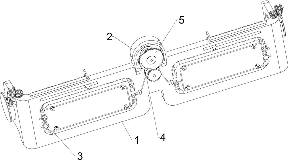
[0026] Such as figure 1 , figure 2 , image 3 , Figure 4 As shown, a medical massage device for eye rehabilitation includes a frame 1, a fixing seat 2, a massage mechanism 3, a pulling mechanism 4, and a driving mechanism 5. The middle part of the frame 1 is provided with a fixing seat 2, and the frame 1 is left and right symmetrical. A massage mechanism 3 is provided, a pulling mechanism 4 is arranged between the middle part of the picture frame 1 and the massage mechanism 3 , and a driving mechanism 5 is arranged on the upper side of the middle part of the picture frame 1 .
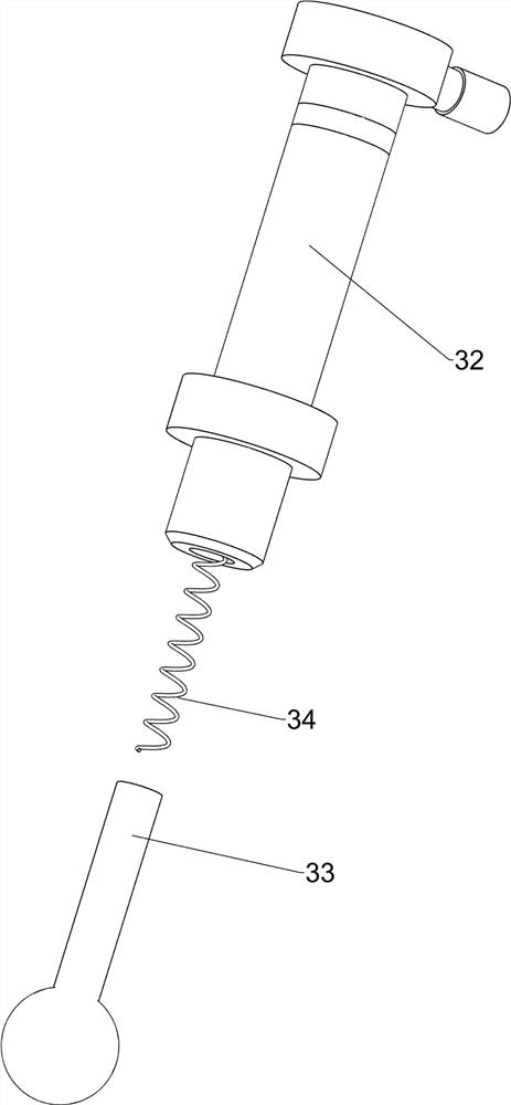
[0027] The massage mechanism 3 includes a slide bar 32, a massage bar 33, a first elastic member 34 and a second elastic member 35, and four U-shaped grooves 31 are opened symmetrically on the left and right sides of the picture frame 1, and a slide bar is arranged in the U-shaped groove 31 to slide. 32. Massage bars 33 are slidingly arranged in the slide bar 32, and a first elastic member 34 is ar...
Embodiment 2
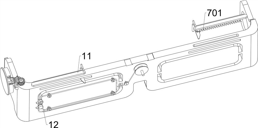
[0032] Such as Figure 4 , Figure 5 , Figure 6 and Figure 7 As shown, on the basis of Embodiment 1, a medical massage device for eye rehabilitation also includes a slider 7, a third elastic member 701, a second rotating shaft 8, a wedge block 9, and a fourth elastic member 10 , a rack 11, a massage stick 1101 and a fixed rod 12, a straight groove 6 is symmetrically opened on the upper side of the picture frame 1 left and right, a slider 7 is slidably arranged in the straight groove 6, and a slider 7 is arranged between the inner wall of the straight groove 6 on the same side There is a third elastic member 701, a second rotating shaft 8 is rotatably arranged on the slider 7, a wedge block 9 is arranged on the lower side of the second rotating shaft 8, and a fourth elastic member 10 is arranged between the wedge block 9 and the slider 7. The top of the two rotating shafts 8 is provided with a rack 11, and the opposite side of the top of the rack 11 is provided with a mass...
PUM
 Abstract
Description
Claims
Application Information
 - R&D
- Intellectual Property
- Life Sciences
- Materials
- Tech Scout
- Unparalleled Data Quality
- Higher Quality Content
- 60% Fewer Hallucinations
Browse by: Latest US Patents, China's latest patents, Technical Efficacy Thesaurus, Application Domain, Technology Topic, Popular Technical Reports.
© 2025 PatSnap. All rights reserved.Legal|Privacy policy|Modern Slavery Act Transparency Statement|Sitemap|About US| Contact US: help@patsnap.com


