
Vertical automatic wire pay-off device without wire spool support

A technology of pay-off device and winding reel, which is applied in the direction of transportation and packaging, delivery of filamentous materials, and thin material processing, etc., which can solve the problems of troublesome disassembly and assembly of winding reels, different thickness of wire coils, and large number of bolts, etc. , to achieve the effect of saving manpower, weight reduction, and more transportation costs

Pending Publication Date: 2021-03-12
YANGZHOU NEW CONCEPT ELECTRIC
View PDF13 Cites 0 Cited by
  • Summary
  • Abstract
  • Description
  • Claims
  • Application Information

AI Technical Summary

Problems solved by technology

[0004] Aiming at the deficiencies of the prior art, the present invention provides a vertical automatic wire pay-off device without the support of the winding reel, which solves the problem that the wires of the existing pay-off mechanism need to be installed on the special winding reel, and provides Due to the different size of the center hole of the wire coil and the different thickness of the wire coil when the material is supplied, it is necessary to customize a suitable winding reel. At the same time, it is very troublesome to disassemble and assemble the special reel. The number of bolts is large, and the electric wires used in another horizontal-axis electric pay-off mechanism come with a reel when ordering. After the wires are used up, the reel will be disposed of as waste products, which is a waste of resources.

Method used


Image

  • Vertical automatic wire pay-off device without wire spool support
  • Vertical automatic wire pay-off device without wire spool support
  • Vertical automatic wire pay-off device without wire spool support

Examples


Embodiment Construction

[0025] The following will clearly and completely describe the technical solutions in the embodiments of the present invention with reference to the accompanying drawings in the embodiments of the present invention. Obviously, the described embodiments are only some, not all, embodiments of the present invention. Based on the embodiments of the present invention, all other embodiments obtained by persons of ordinary skill in the art without making creative efforts belong to the protection scope of the present invention.

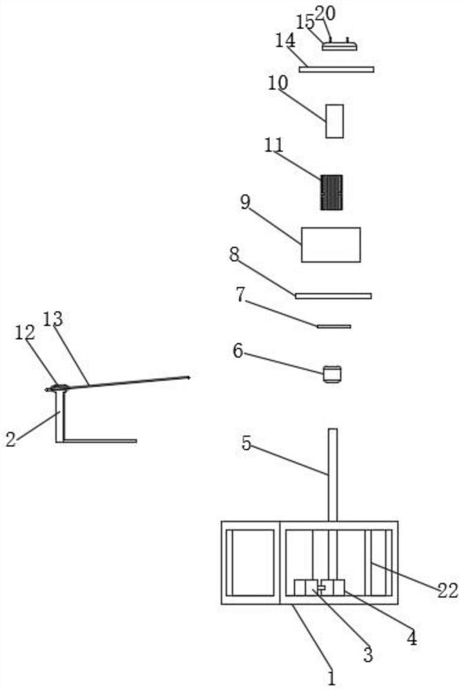
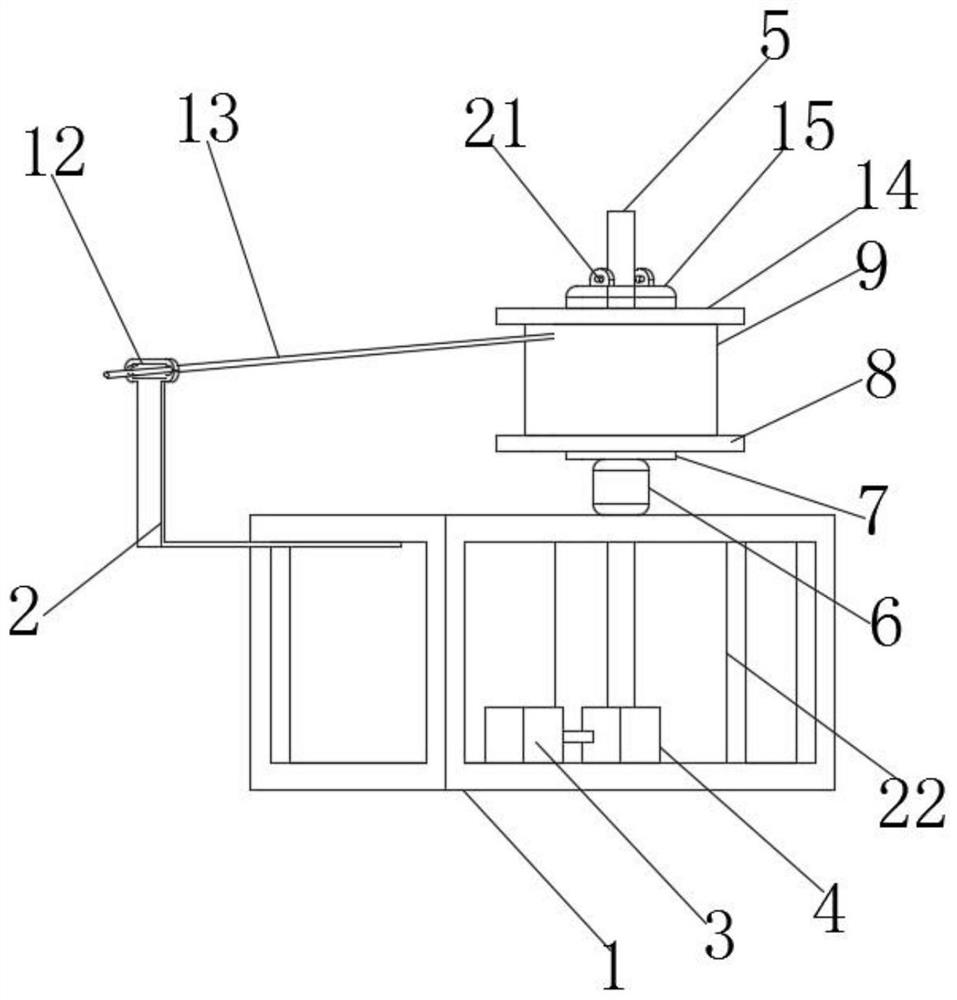
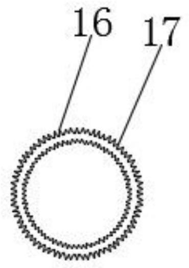
[0026] see Figure 1-4 , the present invention provides a technical solution: a vertical automatic wire pay-off device without winding reel support, comprising a frame 1, the top surface of the frame 1 is fixedly connected with an outlet guide frame 2, and the bottom of the frame 1 is fixed A motor 3 is connected, and the output shaft end of the motor 3 is connected with a reducer 4. The output shaft end of the reducer 4 is fixedly connected with a vertical sh...


PUM


Abstract

The invention discloses a vertical automatic wire pay-off device without wire spool support, and relates to the technical field of wire pay-off. The device comprises a rack, wherein a wire outlet guide frame is fixedly connected to the top surface of the rack, a motor is fixedly connected to the bottom of the rack, a speed reducer is in transmission connection to the output shaft end of the motor,a vertical shaft is fixedly connected to the output shaft end of the speed reducer, and the surface of the vertical shaft is movably connected with a positioning supporting sleeve, a supporting disc,a detachable wire coil tray, a support-free wire coil, centering sponge, a detachable wire coil cover plate and a pressing block in sequence from bottom to top, and the surface of the centering sponge is sleeved with a PVC sleeve. According to the vertical automatic wire pay-off device without the wire spool support, a wire coil without a wire frame can be directly used, a coil fixing frame doesnot need to be specially produced during wire production, the cost is greatly saved, the weight is reduced, the transportation cost can be greatly saved, the abrasion of the PVC sleeve to the outgoingwire of the wire is small, and the quality of the wire in the wire outgoing process is ensured.

Description

technical field [0001] The invention relates to the technical field of wire pay-off, in particular to a vertical automatic wire pay-off device without support from a reel. Background technique [0002] Wire and cable are used to transmit electric (magnetic) energy, information and wire products that realize electromagnetic energy conversion. In the broad sense, wires and cables are also referred to as cables for short. In the narrow sense, cables refer to insulated cables, which can be defined as: a collection composed of the following parts; one or more insulated cores, and their respective possible coatings. The protective layer and the outer sheath, the cable can also have additional uninsulated conductors, the number of cores of common cables and wires is relatively small, generally single core, its cross-sectional area is also small, and has the characteristics of simple structure. There are two common types of electric wires on the market: bv and bvr, and the length o...

Claims


Application Information

Patent Timeline
Patent Type & Authority Applications(China)
IPC IPC(8): B65H49/18B65H49/32B65H57/06B65H67/02
CPCB65H49/18B65H49/32B65H57/06B65H67/02B65H2701/34
Inventor 张莽
Owner YANGZHOU NEW CONCEPT ELECTRIC
Learn More