
Gantry crane

A crane and gantry crane technology, applied in the field of hoisting machinery, can solve the problems of reducing the service life of the hoisting rope, high cost, complex structure, etc., and achieve the effects of perfect function, simple structure, and economical and reasonable layout.

Inactive Publication Date: 2021-03-12
湖南中铁五新重工有限公司
View PDF2 Cites 0 Cited by
  • Summary
  • Abstract
  • Description
  • Claims
  • Application Information

AI Technical Summary

Problems solved by technology

CN202829333U discloses a swing drive mechanism and a crane, which need to be provided with an independent drive device to drive the tilting reel, and the participation of the hoisting reel and the hoisting rope, which not only has a complex structure and high cost, but also reduces the weight of the hoisting rope. service life
But in fact, there is no economical and reasonable gantry crane with multiple functions of lifting, anti-sway, and tilting to meet this growing demand.

Method used


Image

  • Gantry crane
  • Gantry crane
  • Gantry crane

Examples


Embodiment

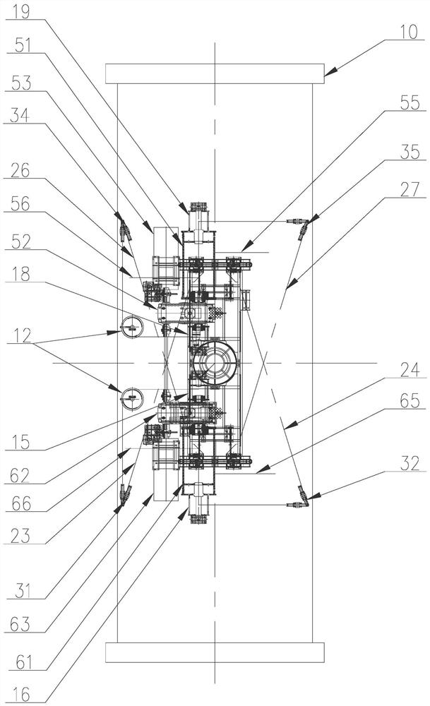
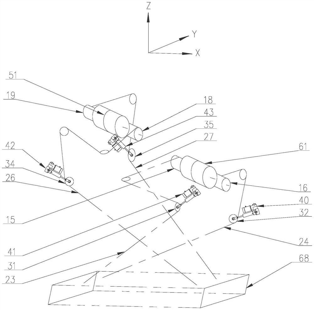
[0039] Such as figure 1 with figure 2 As shown, the gantry crane of this embodiment includes a spreader system, a trolley frame and two pairs of anti-rolling units, and a hoisting mechanism connecting the spreader system and the trolley frame is installed on the trolley frame.

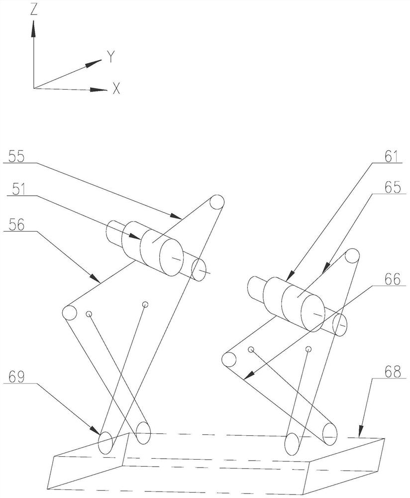
[0040] Such as image 3 As shown, the hoisting mechanism includes a hoisting drum, a hoisting rope wound on the hoisting drum, and two hoisting pulleys arranged on the spreader system. Let the axial direction of the lifting drum be the X direction, let the direction perpendicular to the horizontal plane and the X direction be the Y direction, let the lifting direction be the Z direction, and set the X direction along the direction of the cart or the direction of the trolley; The pulleys are arranged at intervals along the Y-axis direction; the two outgoing rope ends of the hoisting rope are respectively fixed on the trolley frame after bypassing the hoisting pulleys in the direction opposite to its ...


PUM


Abstract

The invention discloses a gantry crane. The gantry crane comprises a lifting appliance system, a trolley frame and two pairs of stabilization units. A lifting winding drum is arranged on the trolley frame. Each stabilization unit comprises a stabilization winding drum, a stabilization rope, a swing pulley and a swing driving mechanism, wherein the stabilization winding drum is fixed to the liftingwinding drum and coaxially arranged with the lifting winding drum; and the stabilization rope sequentially bypasses the stabilization winding drum and the swing pulley to be steered and then is connected with the lifting appliance system. Portions, between the swing pulley and the lifting appliance system, of stabilization ropes are set as stabilization sections, the stabilization sections of thetwo paired stabilization units are located in different vertical planes, and projections of the two stabilization sections in the same X-Z plane are crossed; the swing pulleys of the two paired stabilization units are arranged at intervals in the X-axis direction, and the two pairs of stabilization sections are arranged at intervals in the Y direction; and the swing driving mechanisms are used for driving the corresponding swing pulleys to wind or unwind the ropes. The gantry crane not only can realize the functions of stabilization and lifting appliance tilting and rotation, but also has theadvantages of simple structure and low cost.

Description

technical field [0001] The invention relates to the technical field of hoisting machinery, in particular to a gantry crane. Background technique [0002] After the container ship docks, the lifting equipment on the wharf is required to efficiently unload the containers on the ship to the shore. The equipment used mainly includes shore-to-shore container gantry cranes (hereinafter referred to as quay cranes), rail-mounted container gantry cranes (hereinafter referred to as gantry cranes) and so on. When the crane loads, unloads and lifts the container, it needs to have anti-sway function to restrain the sway of the container and the spreader system; and also needs to have the tilting function, that is, the spreader system can be tilted ±3° along the direction of the trolley and tilted along the direction of the cart. The functions of ±3° and ±5° rotation in the horizontal plane are adapted to the shaking of the ship. [0003] The lifting mechanism of the quay crane is not o...

Claims


Application Information

Patent Timeline
Patent Type & Authority Applications(China)
IPC IPC(8): B66C13/06B66C13/08B66C11/20
CPCB66C11/20B66C13/06B66C13/08
Inventor 江富豪祁加勇袁光金汤应福谢斯垚
Owner 湖南中铁五新重工有限公司
Learn More