
A compacting device for electric power construction

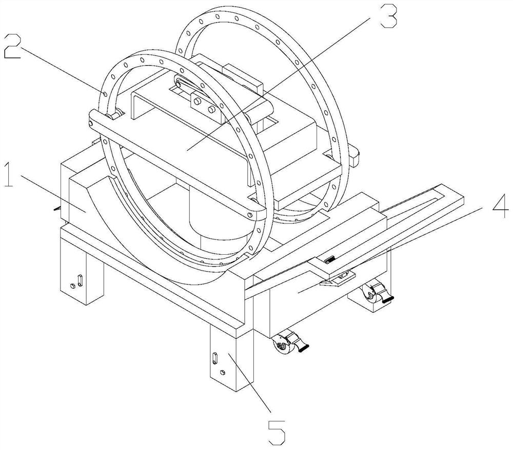
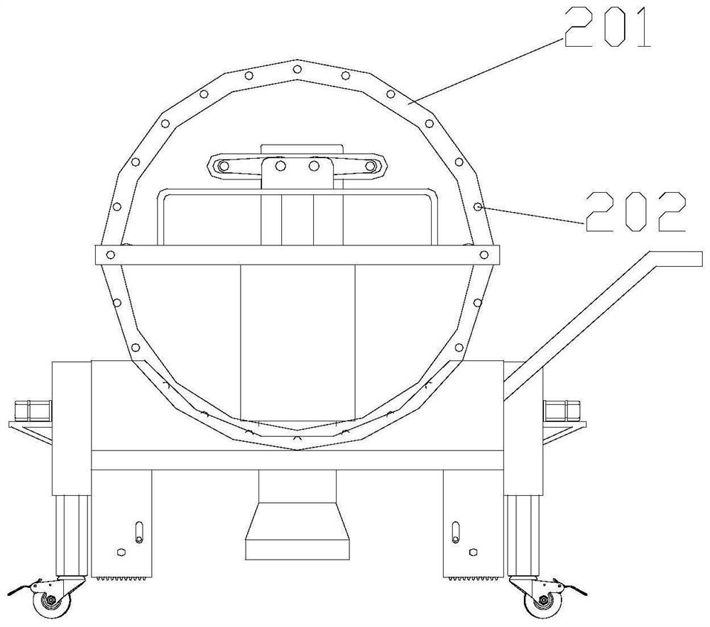
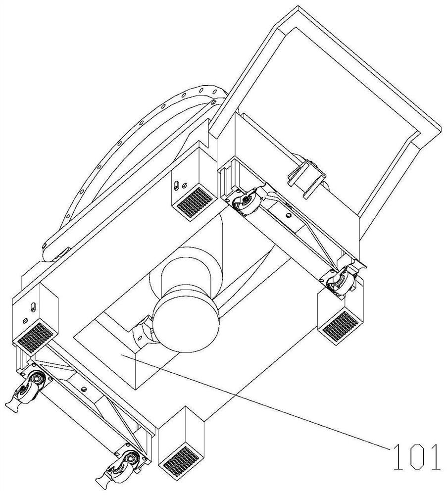
A tamping device and electric power construction technology, which is applied in the direction of infrastructure engineering, towers, building types, etc., can solve the problems of reducing the service life of the support frame, complicated manual tamping process, and inability to perform tamping operations, so as to reduce the anti-seismic force, Improve tamping efficiency and ensure the effect of tamping quality

Active Publication Date: 2022-01-21
STATE GRID SHANDONG ELECTRIC POWER CO TAOXIAN POWER SUPPLY CO
View PDF12 Cites 0 Cited by
  • Summary
  • Abstract
  • Description
  • Claims
  • Application Information

AI Technical Summary

Problems solved by technology

In the current electric power engineering construction, there are usually two methods of manual compaction and mechanical compaction for pole pit compaction. The manual compaction process is complicated, time-consuming and laborious, and the work intensity is high. The tamping hammer is fixed. Because the tamping hammer has its own weight, the tamping hammer must always be kept perpendicular to the horizontal surface. When it is necessary to perform tamping operations on an inclined surface, the tamping hammer will exert greater pressure on the support frame. The support frame is damaged, greatly reducing the service life of the support frame and increasing production costs. The existing tamping device does not have an adjustment mechanism. If the tamping device is on complex terrain, the stability of the tamping device cannot be guaranteed, and the tamping operation cannot be performed, which greatly reduces work efficiency.

Method used


Image

  • A compacting device for electric power construction
  • A compacting device for electric power construction
  • A compacting device for electric power construction

Examples


Embodiment Construction

[0035] Attached below Figure 1-12 , clearly and completely describe the technical solutions in the embodiments of the present invention, obviously, the described embodiments are only some of the embodiments of the present invention, not all of them. Based on the embodiments of the present invention, all other embodiments obtained by persons of ordinary skill in the art without making creative efforts belong to the protection scope of the present invention.

[0036] In describing the present invention, it should be understood that the terms "longitudinal", "transverse", "upper", "lower", "front", "rear", "left", "right", "vertical", The orientations or positional relationships indicated by "horizontal", "top", "bottom", "inner", "outer", etc. are based on the orientations or positional relationships shown in the drawings, and are only for the convenience of describing the present invention, rather than indicating or It should not be construed as limiting the invention by impl...


PUM


Abstract

The invention discloses a compacting device for electric power construction, which comprises a first support frame, on which two traveling mechanisms, four adjustment mechanisms and a fixing frame are installed, and a strip is opened in the middle of the first support frame. shaped hole, the fixed frame is equipped with a tamping mechanism, the tamping mechanism is matched with the bar-shaped hole, the two walking mechanisms are installed at both ends of the first support frame, and the four adjustment mechanisms are installed on the first The four corners of the support frame. The present invention can always ensure that the tamping hammer is in a vertical state with the horizontal plane, ensures the tamping effect and the safety of the first support frame, greatly guarantees the service life of the device, and the adjustment mechanism can adjust the device to ensure the stability of the device , to ensure that the device can adapt to different terrains and improve work efficiency.

Description

technical field [0001] The invention belongs to the technical field of electric power construction, in particular to a compacting device for electric power construction. Background technique [0002] Electric power engineering refers to engineering related to the production, transmission, and distribution of electric energy. In a broad sense, it also includes engineering that uses electricity as power and energy in various fields. In the current electric power engineering construction, there are usually two methods of manual compaction and mechanical compaction for pole pit compaction. The manual compaction process is complicated, time-consuming and laborious, and the work intensity is high. The tamping hammers are all fixed. Because the tamping hammer has its own weight, the tamping hammer must always be kept perpendicular to the horizontal plane. When it is necessary to perform tamping operations on an inclined surface, the tamping hammer will exert greater pressure on the...

Claims


Application Information

Patent Timeline
Patent Type & Authority Patents(China)
IPC IPC(8): E02D3/046E02D3/074E04H12/34
CPCE02D3/046E02D3/074E04H12/34
Inventor 黄大鹏刘普亮王昆立秦岭李玉哲万明高洁孙桂花徐龙广
Owner STATE GRID SHANDONG ELECTRIC POWER CO TAOXIAN POWER SUPPLY CO
Learn More