
Transmission mechanism for realizing spherical circle revolution as well as stirring machine, camera and massager provided with transmission mechanisms correspondingly

A technology of transmission mechanism and rotating shaft, which is applied in the fields of cameras, mixers, and massagers, and can solve problems such as difficulty in achieving ideal fit, lack of versatility, and affecting massage effects, etc.

Pending Publication Date: 2021-03-12
郑文凯
View PDF0 Cites 1 Cited by
  • Summary
  • Abstract
  • Description
  • Claims
  • Application Information

AI Technical Summary

Problems solved by technology

[0016] In the market, the contacts on the massage head are universally designed for a wide range of people, but in real life, everyone’s height, fat, thin, and body structure will have certain differences. The contacts on the massage head and the contact parts of the human body It is difficult to achieve an ideal fit, which will affect the massage effect; in addition, the current massagers are usually designed for a specific part of the human body, and are limited to specific parts and have no versatility. Therefore, different parts of the human body need to be equipped with different types. massager

Method used


Image

  • Transmission mechanism for realizing spherical circle revolution as well as stirring machine, camera and massager provided with transmission mechanisms correspondingly
  • Transmission mechanism for realizing spherical circle revolution as well as stirring machine, camera and massager provided with transmission mechanisms correspondingly
  • Transmission mechanism for realizing spherical circle revolution as well as stirring machine, camera and massager provided with transmission mechanisms correspondingly

Examples


Embodiment Construction

[0046]The following will clearly and completely describe the technical solutions in the embodiments of the present invention with reference to the drawings in the embodiments of the present invention. Apparently, the described embodiments are only some of the embodiments of the present invention, but not all of them. Based on the embodiments of the present invention, all other embodiments obtained by persons of ordinary skill in the art without creative efforts fall within the protection scope of the present invention.

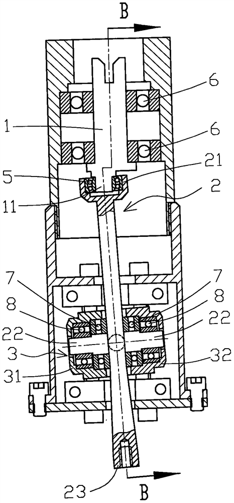
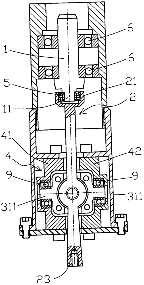
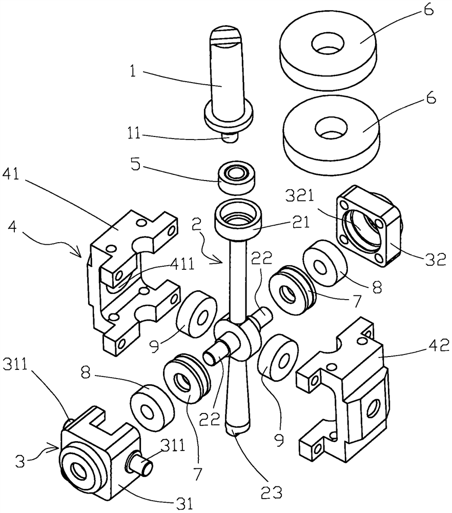
[0047] see Figure 1 to Figure 3 , which is a transmission mechanism for realizing spherical revolution provided by the first embodiment of the present invention, including a rotating shaft 1, a revolving shaft 2, an inner casing 3, and an outer casing 4. The front end of the rotating shaft 1 is provided with the tail of the revolving shaft 2 21 connected to the cylindrical eccentric body 11, the middle part of the revolution shaft 2 is provided with a revolu...


PUM


Abstract

The invention discloses a transmission mechanism for realizing spherical circle revolution as well as a stirrer, a camera and a massager provided with the transmission mechanisms correspondingly. Thetransmission mechanism for achieving spherical circle revolution comprises a rotating shaft, a revolution shaft, an inner shell and an outer shell, a cylindrical eccentric body at the front end of therotating shaft is connected with the tail of the revolution shaft, a revolution fulcrum shaft in the middle of the revolution shaft is connected with an inner shell bearing hole of the inner shell, and an inner shell fulcrum shaft which perpendicularly intersects with the axis of the revolution fulcrum shaft and is positioned outside the inner shell is connected with an outer shell bearing hole of the outer shell. According to the invention, firstly, the transmission mechanism capable of converting rotary motion into spherical circle revolution motion is provided; secondly, the stirrer whichcan improve the stirring uniformity and can be used for carrying out a parallel test is provided; thirdly, the camera capable of expanding the monitoring range and avoiding a monitoring blind area isprovided; and fourthly, the massager which not only can improve the massage effect, but also has universality is provided.

Description

technical field [0001] The present invention relates to the technical field related to mechanical transmission, in particular to a transmission mechanism for realizing spherical revolution and a mixer, a camera and a massager equipped with the transmission mechanism. Background technique [0002] Background technology 1 [0003] The transmission mechanism is to transmit power from one part of the machine to another part, and the component or mechanism that makes the machine or machine parts move or operate is called the transmission mechanism. The selection of the transmission mechanism should proceed from the actual situation and select the appropriate transmission mechanism according to the occasion. [0004] The spherical circle refers to the intersection circle when the spherical surface intersects the plane in space. It is a transmission mechanism that converts the rotational motion into a revolution motion with the spherical circle as the motion track. It has certain a...

Claims


Application Information

Patent Timeline
IPC IPC(8): F16H25/16F16M11/06H04N5/225B01F7/30B01F15/00A61H7/00
CPCF16H25/16F16M11/06A61H7/004A61H2201/1207A61H2201/14B01F27/2322B01F27/85B01F27/951B01F35/322B01F35/31B01F35/30B01F2101/23H04N23/50
Inventor 郑文凯
Owner 郑文凯
Learn More