Current sensor

A current sensor, magnetoelectric technology, applied in the direction of conversion sensor output, voltage/current isolation, instruments, etc., can solve unexpected problems and other problems

Pending Publication Date: 2021-03-12
AISIN CORP
View PDF3 Cites 0 Cited by
  • Summary
  • Abstract
  • Description
  • Claims
  • Application Information

AI Technical Summary

Problems solved by technology

Therefore, at this point, there is still room for improvement in the miniaturization of the device
In addition, in the technology described in Patent Document 3, the influence of the magnetic field from the adjacent current path is reduced by arranging the current path to be measured.

Method used


Image

  • Current sensor
  • Current sensor
  • Current sensor

Examples


Embodiment Construction

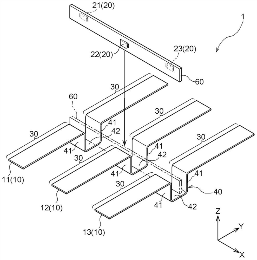
[0027] The current sensor according to the invention is compactly constructed without using a core. Hereinafter, the current sensor 1 of this embodiment will be described. Here, when a current flows through the conductor, a magnetic field is generated with the conductor as the axis according to the magnitude of the current (Ampere's right-hand law). The current sensor 1 detects the magnetic flux density of the magnetic flux in such a magnetic field, and measures the current (current value) flowing through the conductor based on the detected magnetic flux density.

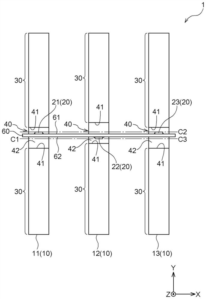
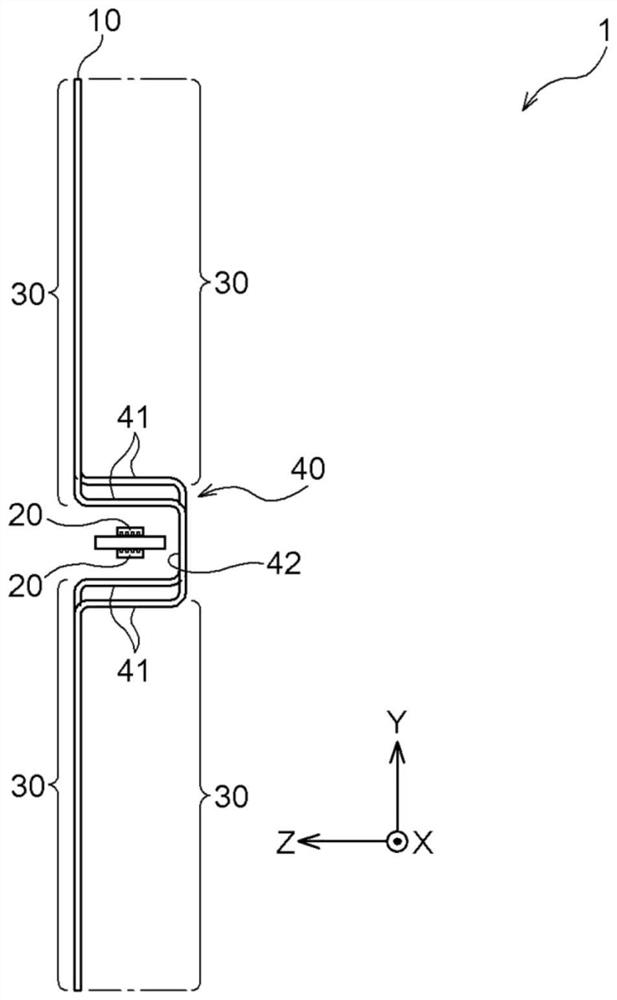
[0028] figure 1 is the expanded view of the current sensor 1, figure 2 is the top view of the current sensor 1, image 3 is a side view of the current sensor 1 . The current sensor 1 is configured to include at least two conductors 10 and at least two magnetoelectric conversion units 20 .

[0029] In the present embodiment, the description is made on the basis of the case where at least two conductors 10 are t...


PUM


Abstract

Provided is a compact current sensor that detects current flowing through each of a plurality of conductors. The current sensor includes at least two conductors and at least two magnetoelectric conversion units each having at least two magnetism detection elements for detecting magnetic flux density of magnetic flux input to detection surfaces facing the same direction, and outputting a signal according to a difference in magnetic flux density between orthogonal components orthogonal to the detection surface of magnetic flux input to the detection surface of the magnetism detection elements. Each conductor includes an extending protrusion portion extending along a second-direction orthogonal to a first-direction being an adjacent direction of two adjacent conductors, and a recessed portionincluding orthogonal portions extending along a third-direction orthogonal to the first- and second-directions and recessed in the third-direction from the extending portion. Each magnetoelectric conversion unit is disposed with the detection surface facing the orthogonal portion of the recessed portion.

Description

technical field [0001] The present invention relates to a current sensor for detecting current flowing in a conductor. Background technique [0002] Conventionally, when measuring the current flowing through the conductor, the magnetic flux density of the magnetic field generated around the conductor corresponding to the current flowing through the conductor is detected by a magnetic detection element, and based on the detected magnetic field Flux density calculation and find the current applied to the conductor. Current sensors using such a technique are described, for example, in Patent Documents 1 to 3 whose references are given below. [0003] Patent Document 1 discloses a current sensor for measuring a current flowing through a conductor. This current sensor is configured to include a U-shaped core as a magnetic body, a conductor inserted through a slit of the core, and a detection element arranged in the slit of the core to detect a magnetic field. [0004] Patent D...

Claims


Application Information

Patent Timeline
Patent Type & Authority Applications(China)
IPC IPC(8): G01R15/20G01R1/18G01R1/16
CPCG01R15/207G01R1/18G01R1/16G01R15/148G01D5/145
Inventor 小泉望
Owner AISIN CORP
Why Eureka
Try Eureka