Eureka AIR delivers breakthrough ideas for toughest innovation challenges, trusted by R&D personnel around the world.

Intelligent equipment remote controller

A technology of remote controller and intelligent equipment, applied in electrical equipment structural parts, electrical equipment housing/cabinet/drawer, cooling/ventilation/heating renovation, etc., can solve problems affecting equipment operation, inconvenient replacement or maintenance, overheating, etc. , to achieve the effect of convenient use, simple operation and convenient use

Inactive Publication Date: 2021-03-12
王纪华
View PDF0 Cites 5 Cited by
  • Summary
  • Abstract
  • Description
  • Claims
  • Application Information

AI Technical Summary

Problems solved by technology

[0004] The purpose of the present invention is to solve the shortcomings of the existing remote controllers, which are very inconvenient when replacing or maintaining the workplace due to their large equipment, and are prone to overheating, which affects the operation of the equipment. A remote controller for intelligent equipment is proposed.

Method used

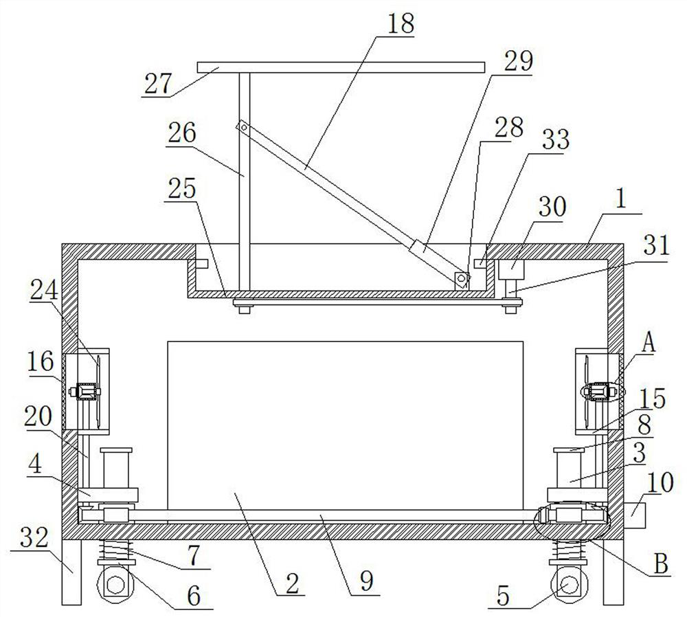

Image

  • Intelligent equipment remote controller
  • Intelligent equipment remote controller
  • Intelligent equipment remote controller

Examples


Embodiment 1

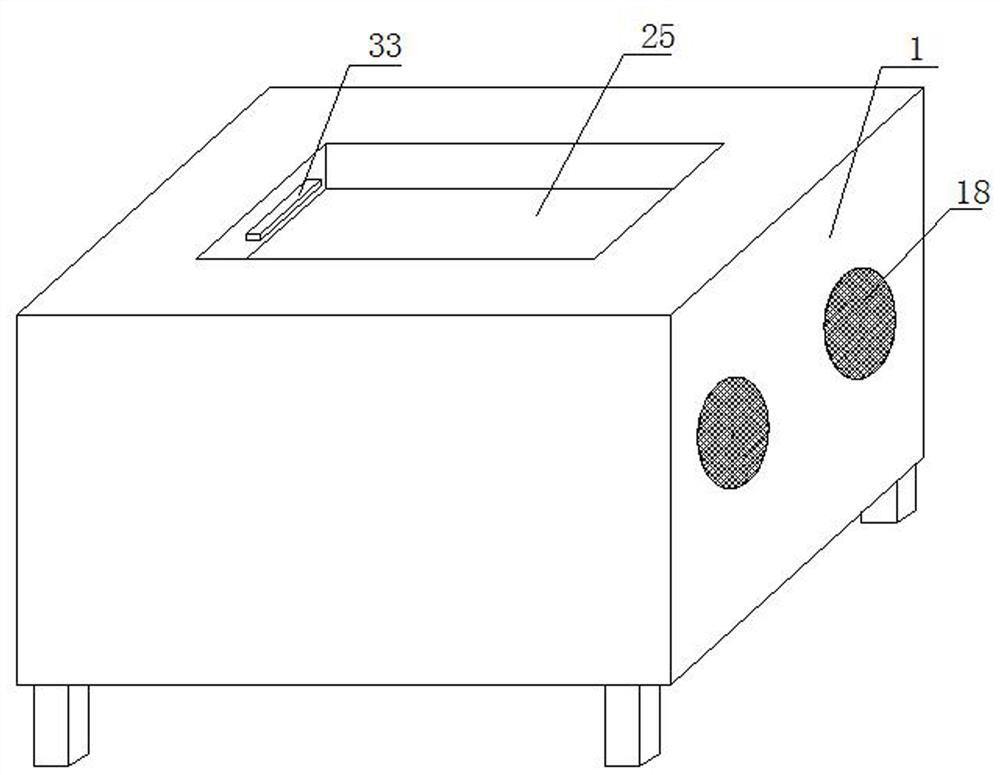
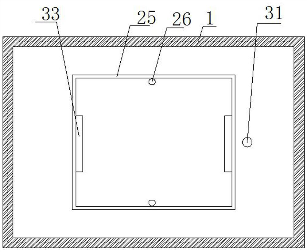
[0029] Refer Figure 1-5 A smart equipment remote controller, including housing 1, and a controller 2 is attached to the bottom of the housing 1, and the bottom sliding of the housing 1 has four symmetrical arranged support rods 3, support rod 3. The bottom rotation is connected to the universal wheel 5, and one side of the housing 1 is fixedly mounted having the first motor 10, and the inner wall of the casing 1 rotates two first rods 9, the first rotor 9 and the corresponding two. A support rod 3 is driven, and two inside the inner wall of the housing 1 are fixedly mounted, and two symmetrical arranged air-blow tubes 15, and the inner wall of the vent pipe 15 is fixedly mounted, and the fixed bar 17 is rotated. Connecting a spindle 19, one end of the rotating shaft 19 is fixedly mounted having a fan blade 24 having a top inner wall of the housing 1 is attached to a place box 25 having a top having an opening, and a display screen 18 is active within the placing cartridge 25.

[0...

Embodiment 2

[0040] Refer Figure 1-5A intelligent equipment remote controller, including a housing 1, and a controller 2 is fixed by a bolt, and the bottom sliding of the housing 1 has four symmetrical setting support rods 3, support rods. 3 The bottom rotation is rotated with a universal wheel 5, and one side of the housing 1 is fixed by a bolt, and the inner wall of the housing 1 rotates two first rods 9, and the first rotor 9 and corresponding The two support rods 3 are connected, and there are two-side inner walls of the housing 1, and two symmetrical disposed air wind tubes 15, and the inner walls of the vent pipe 15 are welded to have a fixed bar 17, and the fixing rod 17 is rotated. Connecting a spindle 19, one end of the rotating shaft 19 is welded with a fan blade 24, and the top inner wall of the housing 1 is welded to a placement cartridge 25 having an opening, and a display screen 18 is active within the placement cassette 25.

[0041] In this embodiment, the first rotary rod 9 is ...


PUM


Abstract

The invention belongs to the technical field of remote controllers, particularly relates to an intelligent equipment remote controller, and aims to solve the problems that it is quite inconvenient toreplace or maintain an existing remote controller in a working place due to large equipment, overheat is easy to form, and equipment operation is affected. According to the invention, the remote controller comprises a shell. A controller is fixedly installed at the bottom of the shell, four symmetrically-arranged supporting rods are slidably connected to the bottom of the shell, universal wheels are rotatably connected to the bottoms of the supporting rods, a first motor is fixedly installed on one side of the shell, two first rotating rods are rotated on the inner wall of the shell, and the first rotating rods are in transmission connection with the two corresponding supporting rods. The inner walls of two sides of the shell are each fixedly provided with two symmetrically-arranged air guide pipes. Th remote controller is easy to operate and convenient to use, the remote controller can be conveniently moved, meanwhile, the remote controller can be stably placed during work, ventilation and heat dissipation can be achieved, a display screen can be conveniently stored and protected, and people can use the remote controller conveniently.

Description

Technical field [0001] The present invention relates to the technical field of remote controller, and more particularly to a smart equipment remote controller. Background technique [0002] Remote control equipment remote device monitoring platform, remote device operation and maintenance and smart monitoring help companies solve brand, repair upgrade failure equipment remote monitoring listed companies, positioning data statistics, asset management remote control software, widely used in industries. [0003] Existing remote controllers are extremely inconvenient due to large equipment, and are very inconvenient in working place, and easy to form overheating, affecting equipment operation, so we propose a smart equipment remote controller. Inventive content [0004] It is an object of the present invention to solve the existing remote controller due to the large device, and is very inconvenient in performing a working place, and it is easy to form an overheating, affecting the s...

Claims


Application Information

Patent Timeline
Patent Type & Authority Applications(China)
IPC IPC(8): H05K5/02H05K7/20
CPCH05K5/0217H05K5/0234H05K7/20145H05K7/20172
Inventor 王纪华
Owner 王纪华
Why Eureka
Eureka Blog
Learn More