
Cleaning components and cleaning equipment

A technology for cleaning components and cleaning equipment, which is applied to cleaning equipment, cleaning machinery, carpet cleaning, etc., to achieve the effect of increasing the scope of application and improving the cleaning effect

Active Publication Date: 2022-02-22
MIDEA ROBOZONE TECH CO LTD
View PDF5 Cites 0 Cited by
  • Summary
  • Abstract
  • Description
  • Claims
  • Application Information

AI Technical Summary

Problems solved by technology

[0003] Embodiments of the present application provide a cleaning component and cleaning equipment to solve or alleviate one or more technical problems in the prior art

Method used


Image

  • Cleaning components and cleaning equipment
  • Cleaning components and cleaning equipment
  • Cleaning components and cleaning equipment

Examples


Embodiment Construction

[0048] In the following, only some exemplary embodiments are briefly described. As those skilled in the art would realize, the described embodiments may be modified in various different ways, all without departing from the spirit or scope of the present application. Accordingly, the drawings and descriptions are to be regarded as illustrative in nature and not restrictive.

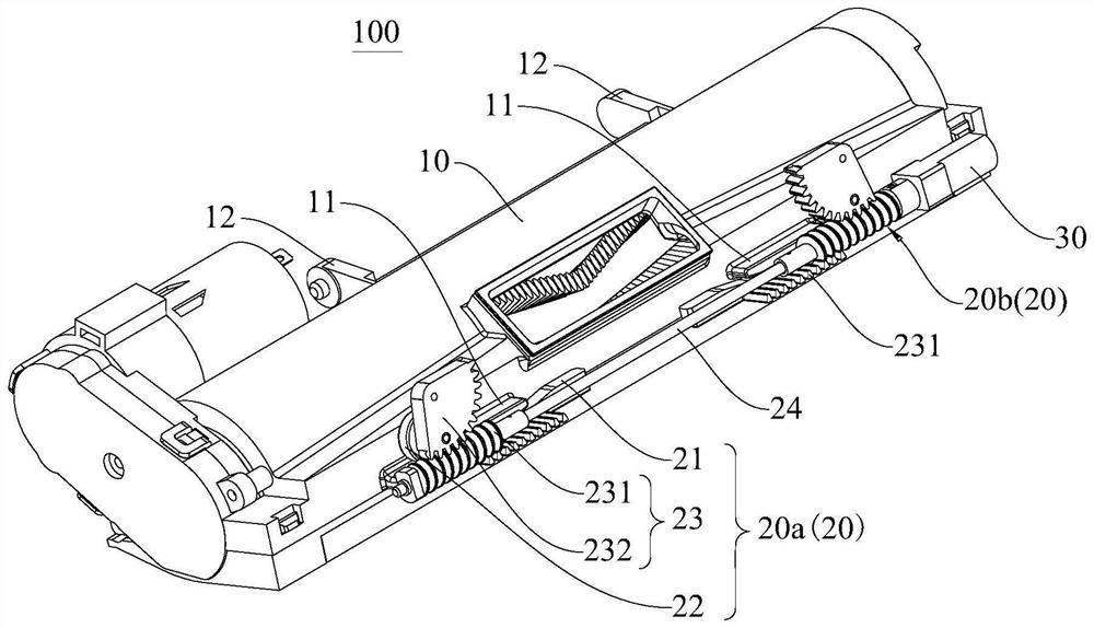
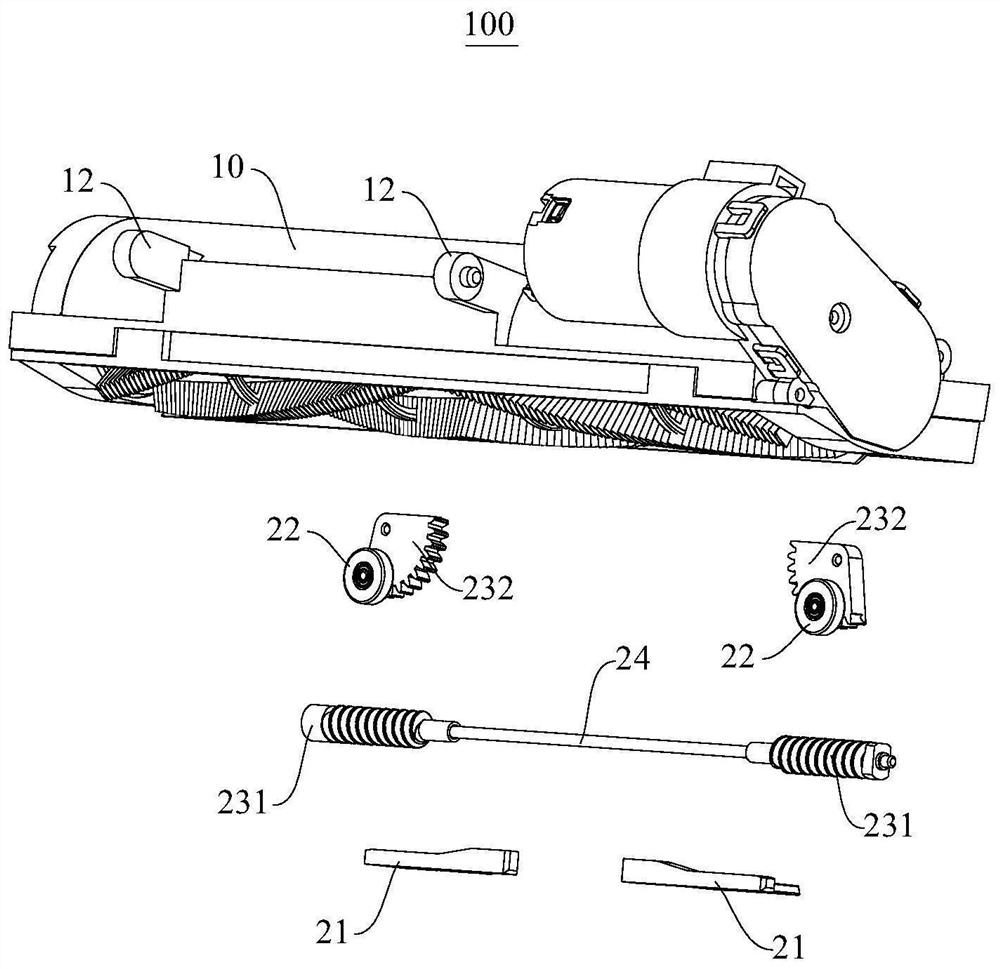
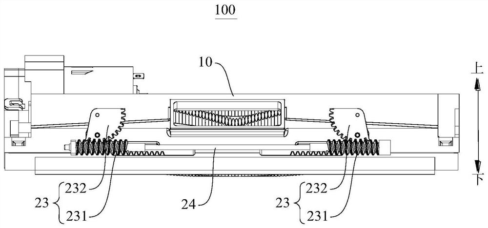
[0049] Refer below Figure 1-Figure 11 A cleaning assembly 100 according to an embodiment of the present application is described. The cleaning assembly 100 according to the embodiment of the present application can be used in the cleaning device 1 to realize the cleaning function of the cleaning device 1 .

[0050] Such as figure 1 with figure 2 As shown, the cleaning assembly 100 includes a cleaning part 10 and a limiting mechanism 20 .

[0051] Specifically, the cleaning part 10 is used to clean the surface to be cleaned, and the cleaning part 10 is provided with limiting ribs 11 . The limiting m...


PUM


Abstract

Embodiments of the present application provide a cleaning component and cleaning equipment. Among them, the cleaning component includes: a cleaning part, which is used to clean the surface to be cleaned, and the cleaning part is provided with a limit rib; a limit mechanism, including a first limit piece, a second limit piece and a transmission assembly, and the transmission assembly drives the second limit The member moves between the first preset position and the second preset position relative to the first limiter; wherein, when the second limiter is at the first preset position, the limit rib is between the first limiter and the second preset position. Locking between the second limiting parts; when the second limiting part is at the second preset position, the limiting rib is movable between the first limiting part and the second limiting part. By adopting the above technical solution, the cleaning part can be fixed relative to the chassis or can be floated relative to the chassis to meet different cleaning requirements, and has the advantages of wide application range and good cleaning effect.

Description

technical field [0001] The present application relates to the technical field of cleaning equipment, in particular to a cleaning component and cleaning equipment. Background technique [0002] In the related art, the cleaning robot performs the cleaning function through a roller brush in contact with the ground, and the roller brush usually adopts a fixed structure or a floating structure. Among them, the roller brush with a fixed structure has problems such as large noise, large movement resistance, and possible scratches when cleaning hard floors such as floors and tiles; the roller brush with a floating structure is used to clean soft floors such as carpets. , there are problems such as poor cleaning effect. Therefore, it is difficult for the cleaning robot in the related art to meet the cleaning requirements of various types of surfaces to be cleaned. Contents of the invention [0003] Embodiments of the present application provide a cleaning component and cleaning e...

Claims


Application Information

Patent Timeline
Patent Type & Authority Patents(China)
IPC IPC(8): A47L11/282A47L11/40
CPCA47L11/282A47L11/40A47L11/4069A47L11/4011
Inventor 郭辉李洋李蒙程福萍
Owner MIDEA ROBOZONE TECH CO LTD
Learn More