Seat frame mounting structure

An installation structure and seat frame technology, applied in the direction of movable seats, etc., can solve the problems of increasing cost, increasing the length of the rear panel of the seat frame, insufficient foot space, etc., so as to increase foot space, strengthen support, reduce The effect of weight

Pending Publication Date: 2021-03-16
CHONGQING YANFENG ADIENT AUTOMOTIVE COMPONENTS CO LTD
View PDF0 Cites 1 Cited by
  • Summary
  • Abstract
  • Description
  • Claims
  • Application Information

AI Technical Summary

Problems solved by technology

[0003]1. When the front of the seat is upturned, the existing support structure cannot guarantee effective support for the front of the seat;
[0004]2. The linkage structure between the seat cushion and the backrest is complicated, and the lower part of the seat usually cannot be rotated, and is separated from the backrest of the seat, so linkage cannot be performed;
[0005] 3. The front part of the lower connection plate of the traditional recliner is directly connected to the side plate of the seat frame, and then the side plate of the seat frame is connected to the slide rail; the position of the recliner is relatively high, and the recliner is located above the seat frame or basically flat Qi, the front space of the seat frame body is small, and the foot space is insufficient
[0006] 4. When increasing the area of ​​the seat frame, it is necessary to increase the length of the rear wall of the seat frame, which increases the cost, increases the weight and occupies space

Method used


Image

  • Seat frame mounting structure
  • Seat frame mounting structure
  • Seat frame mounting structure

Examples


Embodiment Construction

[0047] The present invention will be further described below in conjunction with embodiment and accompanying drawing.

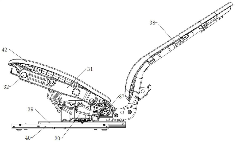
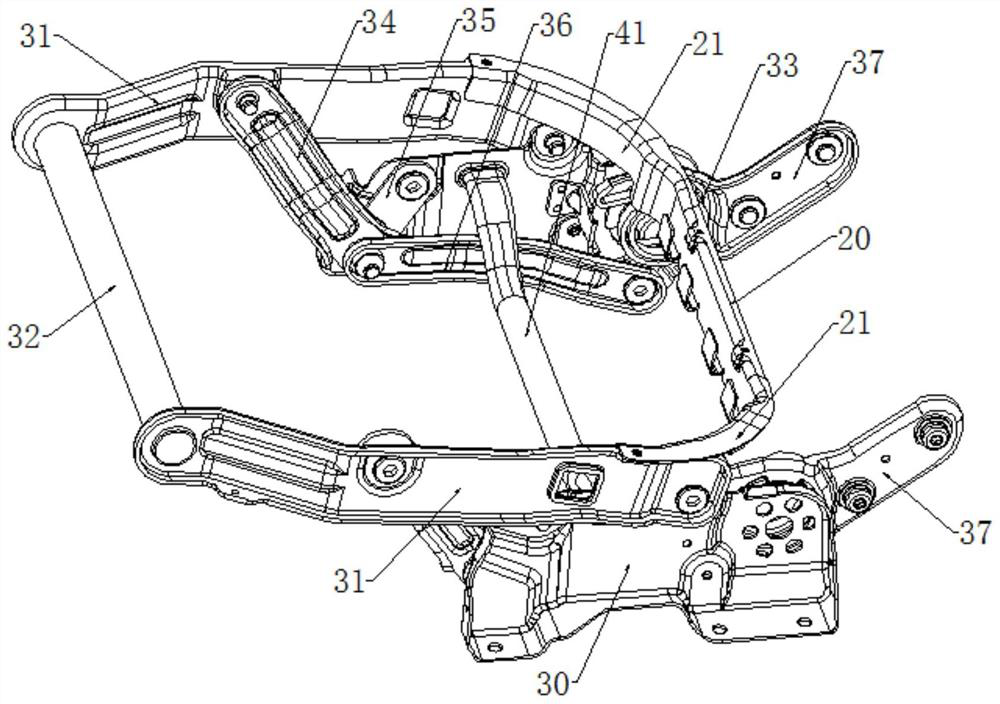
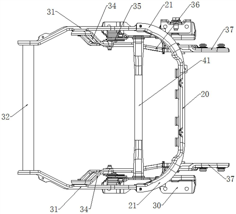
[0048] Such as Figure 1 to Figure 12 As shown, a seat frame installation structure, which mainly includes a seat frame body, a lower connector and a slide rail, is characterized in that: the slide rail is arranged horizontally, the lower connector is installed on the upper surface of the slide rail, The lower connecting piece is located below the seat frame body, and the seat frame body is installed on the slide rail through the lower connecting piece;

[0049] The lower connecting piece includes two recliner lower connecting plates 30 facing oppositely. The main body is connected, and the lower part of the lower connecting plate 30 of the recliner is fixedly connected with the slide rail.

[0050] in:

[0051] The rear part of the seat frame body is connected to the lower connecting plate 30 of the recliner, and the front part of the seat frame body is s...


PUM


Abstract

The invention discloses a seat frame mounting structure which comprises a seat frame body, a lower connecting piece and a sliding rail, and is characterized in that the lower connecting piece is mounted on the upper surface of the sliding rail, the lower connecting piece is located below the seat frame body, the seat frame body is mounted on the sliding rail through the lower connecting piece, andthe lower connecting piece comprises two angle adjuster lower connecting plates which are oppositely arranged; the upper portions of the angle adjuster lower connecting plates are connected with theseat frame body, and the lower portions of the angle adjuster lower connecting plates are fixedly connected with the sliding rail. By the adoption of the seat frame mounting structure, two adjusting plates are obliquely arranged towards the inner side of a side plate body, the supporting of the front portion of a seat can be enhanced, the area of a defined seat frame is increased under the condition that the length of the seat frame rear coaming is not changed, the structure is simple, and the weight of a seat framework is reduced. The seat frame body is directly connected with the angle adjuster lower connecting plates, the angle adjuster lower connecting plates are directly installed on the sliding rail, the front portion of the seat frame body is suspended, and the foot space is enlarged.

Description

technical field [0001] The invention relates to a car seat, in particular to a seat frame installation structure. Background technique [0002] Car seat belongs to the basic device of the car and is an important safety part of the car. In the car, it connects the human body and the body, which is directly related to the comfort and safety of the occupants. With the development of society and the improvement of people's economic level , the penetration rate of automobiles is getting higher and higher. During the use of automobiles, facing different users and different environments, new demands will continue to be generated. Facing various demands, it is necessary to design a large number of For this reason, various new structures have been produced, such as the seat frame with the linkage between the seat and the backrest. When designing this product, due to new requirements and mechanisms, it is necessary to redesign the corresponding New parts, for this reason, when facing...

Claims


Application Information

Patent Timeline
Patent Type & Authority Applications(China)
IPC IPC(8): B60N2/22B60N2/06B60N2/07
CPCB60N2/22B60N2/06B60N2/07
Inventor 惠海岗辛艺龙德学杨双华苟华刚
Owner CHONGQING YANFENG ADIENT AUTOMOTIVE COMPONENTS CO LTD
Why Eureka
Try Eureka