
A gas-electric hybrid braking system

A hybrid brake, gas-electric technology, applied in the direction of brakes, brake transmissions, vehicle components, etc., can solve the problems of accelerating driver fatigue and inconvenient operation, and achieve the effects of reducing driver fatigue, fast response speed and high sensitivity

Active Publication Date: 2021-12-28
ANHUI ANKAI AUTOMOBILE
View PDF6 Cites 0 Cited by
  • Summary
  • Abstract
  • Description
  • Claims
  • Application Information

AI Technical Summary

Problems solved by technology

[0003] At present, the commonly used solution is to add relay valves, quick release valves, trailer valves and other devices in the gas pipeline to advance the braking response. For example, the patent application number CN2017100343383.8 discloses a gas-electric hybrid control system brake system, including air storage tank, electric brake master valve, emergency relay valve, proportional relay valve, service brake chamber, brake and electronic control unit; the electric brake master valve is used to The air source is provided to the emergency relay valve, the emergency relay valve is used to distribute the air source to the proportional relay valve, and the proportional relay valve is used to distribute the air source to the service brake air chamber, the service brake air chamber It is used to brake or release the brake under the action of compressed air; the electric brake main valve is electrically connected to the electronic control unit, and provides braking electric signals to the electronic control unit; the electronic control unit is connected to the electronic control unit The proportional relay valve is electrically connected to control the conduction and closing of the proportional relay valve, which has the characteristics of fast response and good stability, but the existing braking system still requires the driver to step on the brake pedal during braking. The foot valve is very inconvenient to operate and accelerates the driver's fatigue

Method used


Image

  • A gas-electric hybrid braking system

Examples


Embodiment Construction

[0021] The following will clearly and completely describe the technical solutions in the embodiments of the present invention with reference to the accompanying drawings in the embodiments of the present invention. Obviously, the described embodiments are only some, not all, embodiments of the present invention. Based on the embodiments of the present invention, all other embodiments obtained by persons of ordinary skill in the art without making creative efforts belong to the protection scope of the present invention.

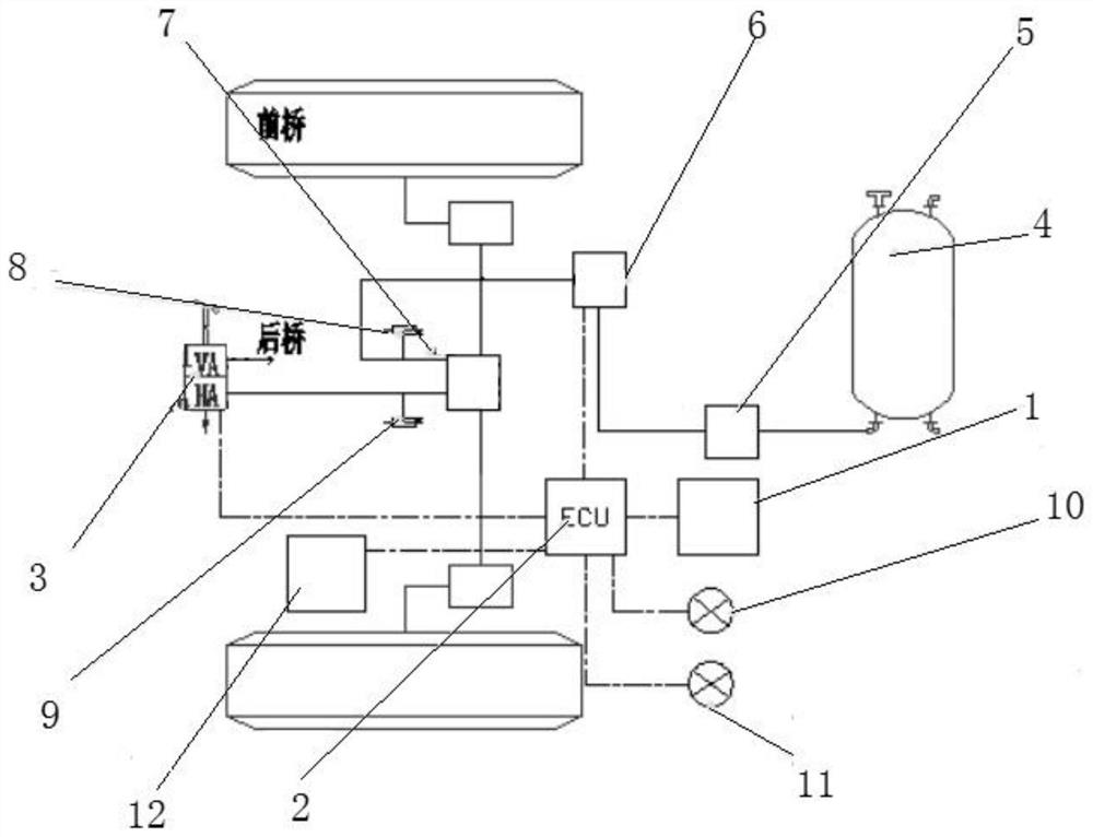
[0022] see figure 1 , in an embodiment of the present invention, a gas-electric hybrid braking system includes a control switch 1, an electronic control unit 2, a foot valve 3, an air reservoir 4, a pressure limiting valve 5, a solenoid valve 6, a two-position three-way valve 7, Sensor one 8, sensor two 9, driving brake lights 10, parking brake lights 11 and accelerator 12, the output end of the air storage tank 4 is connected to the input end of the pressure ...


PUM


Abstract

The invention discloses a gas-electric hybrid brake system, which comprises a control switch, an electronic control unit, a foot valve, an air storage tank, a pressure limiting valve, a solenoid valve, a two-position three-way valve, a sensor one, a sensor two, and a driving brake light , parking brake light and throttle, the output end of the air storage tank is connected to the input end of the pressure limiting valve through the air pipeline, the output end of the limit valve is connected to the input end of the electromagnetic valve through the air pipeline, and the electromagnetic valve The output end of the valve is connected to the input end of the two-position three-way valve through an air pipeline, one interface of the output end of the two-position three-way valve is connected to the input end of the foot valve through an air pipeline, and the output end of the two-position three-way valve The other interface is connected to the front axle through an air pipeline, and the rear axle is connected to the foot valve. The present invention does not need to step on the foot for a long time during the parking process, which can effectively reduce the driver's fatigue.

Description

technical field [0001] The invention belongs to the technical field of braking systems, in particular to a gas-electric hybrid braking system. Background technique [0002] Air brake systems are currently widely used in commercial vehicles. The pneumatic braking system has its unique advantages: 1. It can generate a large braking force; 2. The pipeline structure is simple, and it is convenient to connect and disconnect. However, the traditional pneumatic brake system also has disadvantages. The disadvantage of its own structure is that the brake response time is long. With the increase of the length of the vehicle, the impact of the increase of the braking response time and the increase of the corresponding time difference of each axle braking becomes more and more obvious. [0003] At present, the commonly used solution is to add relay valves, quick release valves, trailer valves and other devices in the gas pipeline to advance the braking response. For example, the paten...

Claims


Application Information

Patent Timeline
Patent Type & Authority Patents(China)
IPC IPC(8): B60T13/68B60T13/74B60Q1/44
CPCB60T13/683B60T13/74B60Q1/441
Inventor 徐凌飞于锋姜琦菲盛明
Owner ANHUI ANKAI AUTOMOBILE
Learn More