Pull-down device of computerized flat knitting machine

A computerized flat knitting and pulling technology, applied in textile and papermaking, weft knitting, knitting and other directions, can solve the problems of complex structure, complicated technical operation and high manufacturing cost of rake rollers, and achieves convenient full-form weaving and sufficient tension. , the effect of low cost

Inactive Publication Date: 2021-03-16
无锡斯拓纺织科技有限公司
View PDF0 Cites 1 Cited by
  • Summary
  • Abstract
  • Description
  • Claims
  • Application Information

AI Technical Summary

Problems solved by technology

[0003] But at present, the rake roller still faces the problems of complex structure, high manufacturing cost, high failure rate, and complicated technical operation

Method used


Image

  • Pull-down device of computerized flat knitting machine
  • Pull-down device of computerized flat knitting machine
  • Pull-down device of computerized flat knitting machine

Examples


Embodiment Construction

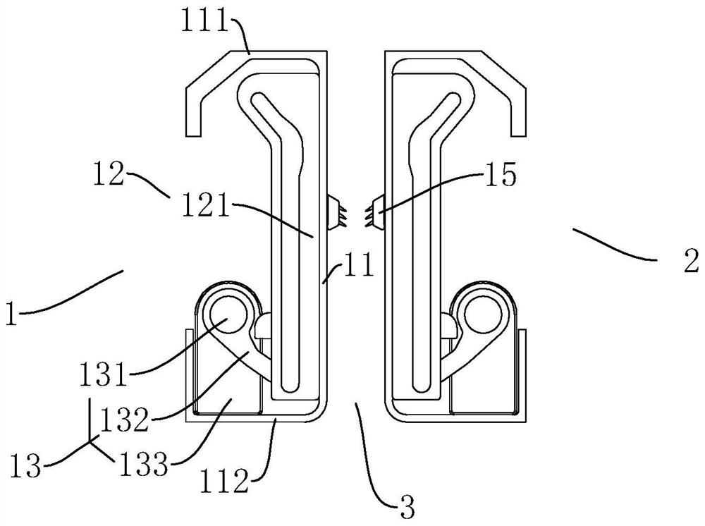
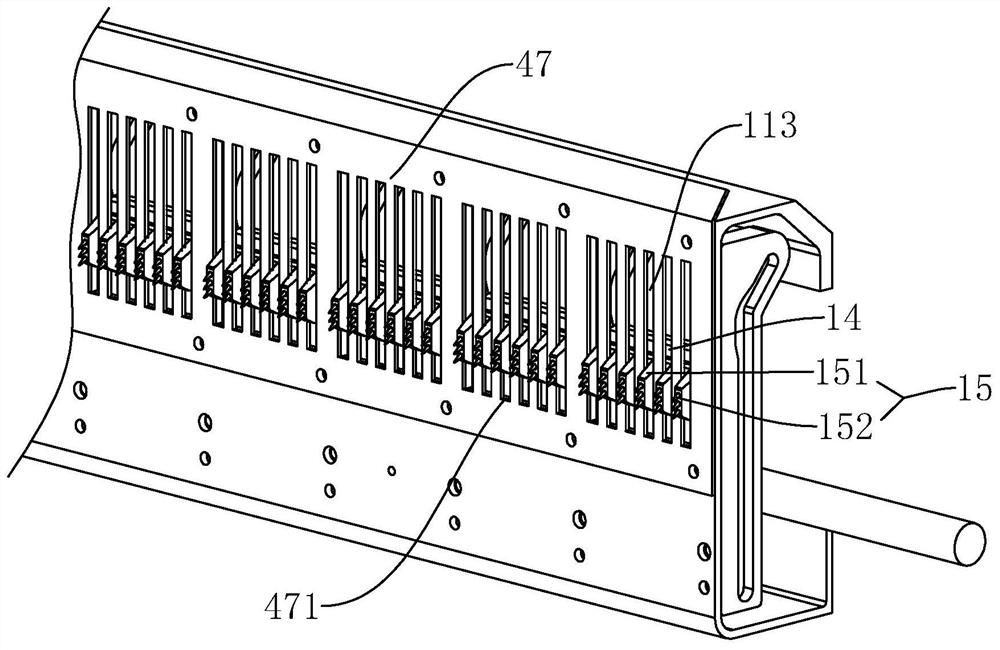
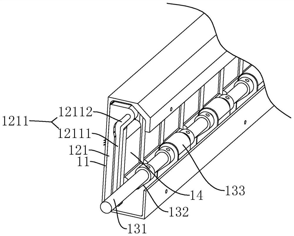
[0032] combine Figure 1 to Figure 7 The pull-down device of the computerized flat knitting machine of the present invention is further described.

[0033] A pull-down device for a computerized flat knitting machine, comprising a left pulling mechanism 1 and a right pulling mechanism 2, the left pulling mechanism 1 and the right pulling mechanism 2 are arranged symmetrically and form a pulling channel 3 for fabrics to pass through. It is characterized in that: the left pulling mechanism 1 and the right pulling mechanism 2 both include a plate frame 11 , a guide assembly 12 , a pulling rake 14 and a driving assembly 13 .

[0034] The plate frame 11 is a strip-shaped structure, on which there are a plurality of windows 113 arranged along the length direction of the plate frame 11, and an upper shielding plate 111 and a lower mounting plate 112 are respectively formed on the upper and lower sides of the back of the plate frame 11; It should be noted that the opposite side of the...


PUM


Abstract

The invention discloses a pull-down device of a computerized flat knitting machine. The pull-down device comprises a left traction mechanism and a right traction mechanism which are symmetrically arranged and form a traction channel therebetween, and is characterized in that each of the left traction mechanism and the right traction mechanism comprises a plate frame, a guide assembly, a traction rake and a driving assembly, wherein a window is formed in the plate frame; the traction rake is installed on the back face of the plate frame in an up-down movable mode through the guide assembly, anda rake nail assembly is arranged on the side wall of the front face of the head of the traction rake and corresponds to the window; the driving assembly is installed on the back face of the plate frame and connected with the tail of the traction rake so as to drive the traction rake to move up and down along a guide track of the guide assembly, the rake nail assembly is guided to the outer side of the plate frame through the guide track when the traction rake moves downwards, and the rake nail assembly is guided to the inner side of the plate frame through the guide track when the traction rake moves upwards. According to the pull-down device, fabric can be uniformly and stably pulled, so that the processing efficiency and quality are improved.

Description

technical field [0001] The invention relates to the technical field of textile machinery, and in particular to a pull-down device for a computerized flat knitting machine. Background technique [0002] Computerized flat knitting machines play a pivotal role in the textile industry due to their high weaving efficiency, low operator requirements and easy programming. The roller is an essential device used to pull the fabric in the computerized flat knitting machine. Its function is to pull the fabric formed by the knitting mechanism downward under the clamping state, so as to facilitate the realization of functions such as knitting and transfer of the latch needle. Computerized flat knitting machines with fully formed functions have developed rapidly in recent years, and are favored by the market because of their advanced integrated garment functions that can get rid of the productivity constraints of traditional sleeve technology. high demands. The existing market focuses o...

Claims


Application Information

Patent Timeline
Patent Type & Authority Applications(China)
IPC IPC(8): D04B15/90
CPCD04B15/90
Inventor 杨冲汉
Owner 无锡斯拓纺织科技有限公司
Why Eureka
Try Eureka