Joint cutting mechanism for small veneers

A cutting mechanism and veneer technology, applied in the direction of making finger joints, etc., can solve the problem of lack of cutting devices, etc., and achieve the effect of improving efficiency and quickly cutting veneer

Inactive Publication Date: 2021-03-19
德清嘉之爵乐器有限公司
View PDF0 Cites 0 Cited by
  • Summary
  • Abstract
  • Description
  • Claims
  • Application Information

AI Technical Summary

Problems solved by technology

After the veneers are planed, they are pieces of shorter veneers, so these veneers need to be spliced ​​and then rolled into veneer rolls, which is convenient for subsequent processing and transportation. When veneers are spliced, the joints of the two veneers need to be Cut into a tooth-shaped structure that matches the shape, thereby improving the splicing strength. Currently, there is still a lack of devices that can quickly cut

Method used


Image

  • Joint cutting mechanism for small veneers
  • Joint cutting mechanism for small veneers

Examples


Embodiment 1

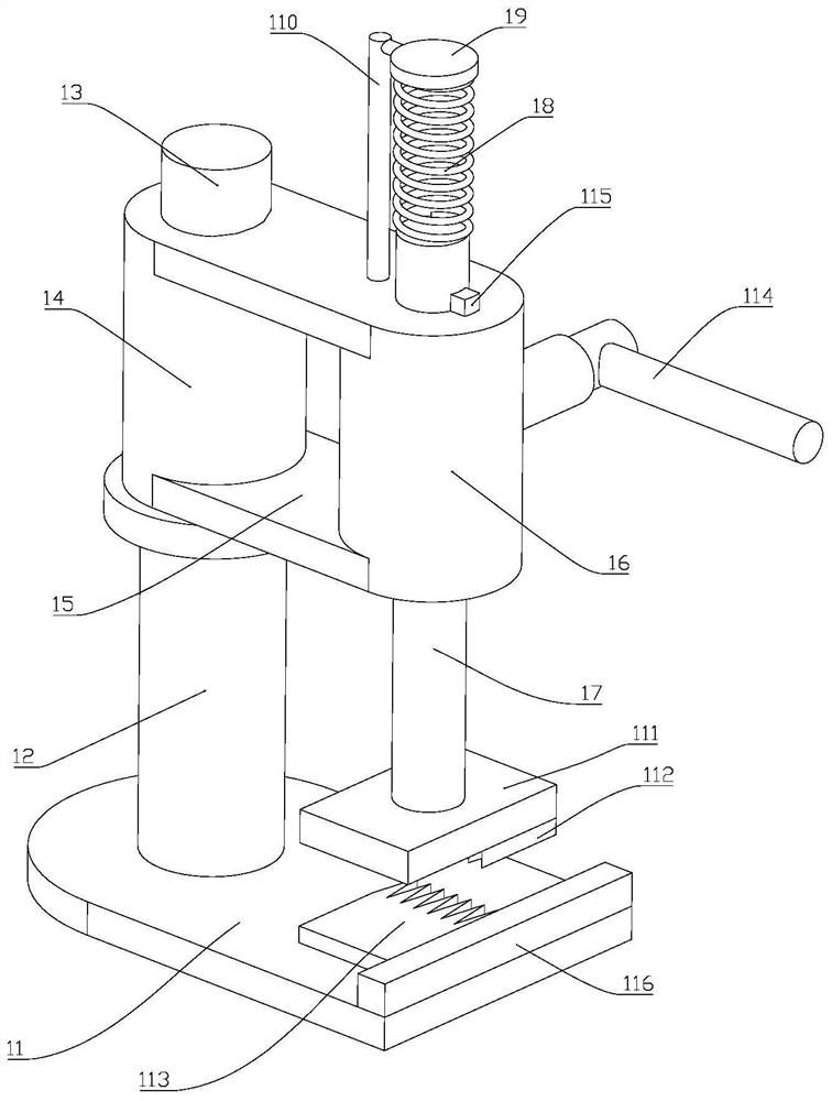
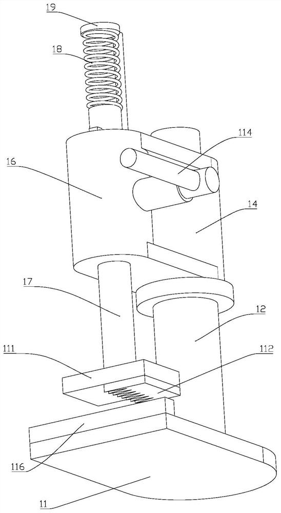
[0015] Such as figure 1 , 2 As shown, a small veneer joint cutting mechanism includes a cutting base 11, and a first support base 12 fixed on the cutting base 11, the top of the first support base 12 is fixed with a first rotating shaft 13, the The first rotating shaft 13 is matched with the first rotating sleeve 14, the first rotating sleeve 14 is fixedly connected with the first sliding sleeve 16 through the first connecting rod 15, and the first rotating sleeve 14 is connected with the first sliding sleeve. The axial directions of the sleeves 16 are parallel to each other. The first sliding sleeve 16 is matched with a first sliding shaft 17 which is relatively slidingly connected with the first sliding sleeve 16 . The top end of the first sliding shaft 17 passes through a first spring 18 Fixedly connected with the first fixing plate 19, the first fixing plate 19 is fixed above the first sliding sleeve 16 through the first support rod 110, the bottom end of the first slidin...


PUM


Abstract

The invention discloses a joint cutting mechanism for small veneers. The joint cutting mechanism comprises a cutting base, a first supporting seat, a first rotating shaft, a first rotating sleeve, a first connecting rod, a first sliding sleeve, a first sliding shaft, a first spring, a first fixing plate, a first supporting rod, a first base, a first tooth-shaped cutter, a second tooth-shaped cutter and a first operating rod. According to the joint cutting mechanism, vertical movement of the first tooth-shaped cutter is realized through the first sliding shaft, the veneers are cut by means of the second tooth-shaped cutter, meanwhile, the first sliding shaft is automatically reset through retraction of the first spring, and therefore the purpose of quickly cutting the veneers is achieved, and the efficiency is greatly improved.

Description

technical field [0001] The invention relates to a small veneer joint cutting mechanism. Background technique [0002] Logs become veneers after being peeled, and large veneers and small wooden belts are used in practical applications. After the veneers are planed, they are pieces of shorter veneers, so these veneers need to be spliced ​​and then rolled into veneer rolls, which is convenient for subsequent processing and transportation. When veneers are spliced, the joints of the two veneers need to be It is cut into a tooth-shaped structure that matches the shape to improve the splicing strength. Currently, there is still a lack of devices that can quickly cut. Contents of the invention [0003] In view of the above problems, the present invention provides a small veneer joint cutting mechanism, which effectively solves the problems pointed out in the background technology. [0004] The technical scheme adopted in the present invention is: [0005] A small veneer joint ...

Claims


Application Information

Patent Timeline
Patent Type & Authority Applications(China)
IPC IPC(8): B27F1/16
CPCB27F1/16
Inventor 徐宁
Owner 德清嘉之爵乐器有限公司
Why Eureka
Try Eureka