Offset type screw pressurization water injection device

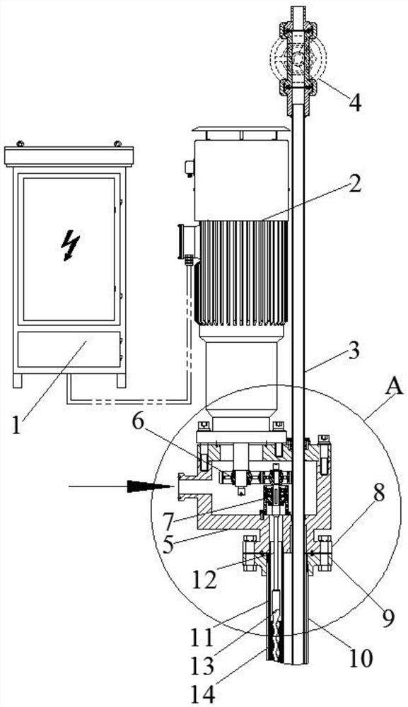
An offset and screw technology, applied in rotary piston pumps, rotary piston machines, rotary piston/oscillating piston pump combinations, etc., can solve the problem of small displacement, small footprint of vertical screw pumps, The vertical screw pump occupies the working channel of the water injection well and other problems, so as to achieve the effect of small footprint, small displacement and simple structure

Pending Publication Date: 2021-03-23
XINXIANG XIAFENG ELECTRIC LTC
View PDF0 Cites 2 Cited by
  • Summary
  • Abstract
  • Description
  • Claims
  • Application Information

AI Technical Summary

Problems solved by technology

[0004] The commonly used vertical screw pump has a small footprint, simple structure, and small displacement, and is suitable for single well injection. The main problem of this water injection method is that the vertical screw pump occupies the working channel of the water injection well, and the water injection well cannot For well washing, well logging, profile control and other operations, the vertical screw pump must be removed from the water injection well every time the well washing, well logging, profile control and other operations are performed, and the well washing and logging can only be performed after the screw pump is pulled out. Well, profile control and other operations

Method used


Image

  • Offset type screw pressurization water injection device
  • Offset type screw pressurization water injection device
  • Offset type screw pressurization water injection device

Examples


Embodiment Construction

[0035] The technical solutions in the embodiments of the present invention will be clearly and completely described below, obviously, the described embodiments are only some of the embodiments of the present invention, not all of the embodiments. All other embodiments obtained by persons of ordinary skill in the art based on the embodiments of the present invention belong to the protection scope of the present invention.

[0036] In the description of the present invention, the terms "longitudinal", "transverse", "upper", "lower", "front", "rear", "left", "right", "vertical", "horizontal", " The orientations or positional relationships indicated by "top", "bottom", etc. are based on the orientations or positional relationships shown in the drawings, and are only for the convenience of describing the present invention and do not require that the present invention must be constructed and operated in a specific orientation, so they cannot be understood as Limitations on the Inven...


PUM


Abstract

The invention provides an offset type screw pressurization water injection device. The offset type screw pressurization water injection device comprises a shell, a screw pump and a well logging pipeline; the shell is in sealing connection with a water injection well; the screw pump is mounted on the shell, extends into the water injection well and is used for injecting water into the water injection well; the well logging pipeline is mounted on the shell, the well logging pipeline and the screw pump go deep into the water injection well in parallel, and the well logging pipeline is used for conducting in-well operation on the water injection well; and injection of the water into the water injection well through the screw pump and in-well operation on the water injection well through a welllogging channel are not conducted at the same time. The offset type screw pressurization water injection device can be directly mounted on the water injection well, well washing, well logging, profile control and other operations can be directly carried out through the well logging channel without detaching the screw pressurization water injection device from a wellhead or pulling out the screw pump, and the operation cost and the operation difficulty are greatly reduced. Meanwhile, after the offset type screw pressurization water injection device is mounted, disassembly is not needed duringvarious operations such as well washing, well logging and profile control every year, the risk that a unit is damaged due to disassembly and assembly of the unit can be greatly reduced, and the stability of the offset type screw pressurization water injection device is guaranteed.

Description

technical field [0001] The invention belongs to the technical field of oilfield water injection, and in particular relates to an offset screw booster water injection device. Background technique [0002] At present, the screw pump is a common pressurized water injection equipment at the end of the oil field. Among them, the screw pump is divided into two types: vertical and horizontal structures. In addition, there are centrifugal pumps, reciprocating pumps and other pressurized water injection equipment. The horizontal screw pressurized water injection device, centrifugal pump and reciprocating pump have a large displacement. Generally, one water injection equipment injects water for multiple water injection wells at the same time; if there is only one water injection well in a well site, a vertical screw pump is generally used to The water injection well is used for pressurized water injection. When in use, the vertical screw pump is directly installed on the wellhead of t...

Claims


Application Information

Patent Timeline
Patent Type & Authority Applications(China)
IPC IPC(8): E21B43/20F04C2/107F04C11/00F04C15/00
CPCE21B43/20F04C2/107F04C11/00F04C15/0061F04C2210/1094
Inventor 宋宇飞魏军青顼栋勾国伟汪洋岳修业熊健伟
Owner XINXIANG XIAFENG ELECTRIC LTC
Why Eureka
Try Eureka